Check patentability & draft patents in minutes with Patsnap Eureka AI!

Rotation stopping mechanism of rotary shaft

A technology for rotating shafts and gears, which is applied in the direction of brake actuators, gear transmission mechanisms, mechanical equipment, etc. It can solve the problems that the rotating shaft cannot be completely locked, the shaft cannot be locked, and the force is not enough, so as to achieve uniform force and good structure. Clean, Controlled, Reliable Effects

Inactive Publication Date: 2017-08-22
CHANGCHUN INST OF OPTICS FINE MECHANICS & PHYSICS CHINESE ACAD OF SCI
View PDF9 Cites 4 Cited by
  • Summary
  • Abstract
  • Description
  • Claims
  • Application Information

AI Technical Summary

Problems solved by technology

[0004] The main problem with this anti-rotation mechanism is that the rotating shaft cannot be completely locked
Due to the limitation of the installation space, the outer diameter of the pull-type electromagnet 6 can no longer be enlarged, thus, the suction force of the pull-type electromagnet 6 is also limited, so that the compression force of the compression spring 5 cannot be increased, and the stop rod 1 When the teeth and the teeth of the stop gear 4 are inserted together, the strength is not enough. When the external environment vibrates, the rotating shaft will eventually turn to one side and turn to the free end of the stop gear rod 1, which cannot achieve the purpose of locking the shaft.

Method used


Image

  • Rotation stopping mechanism of rotary shaft
  • Rotation stopping mechanism of rotary shaft
  • Rotation stopping mechanism of rotary shaft

Examples


Embodiment Construction

[0018] The present invention will be described in detail below with reference to the accompanying drawings and examples.

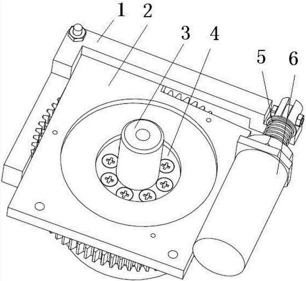
[0019] as attached figure 2 with 3 As shown, the present invention provides an anti-rotation mechanism for a rotating shaft, which includes a fixed plate 2, a gear stop rod 1, a stop gear 4, a rotating shaft 3, a compression spring 5, a push electromagnet 8 and a magnetic core 7;

[0020] The two ends of the stop gear rod 1 have a connection structure, and the middle section of the stop gear rod 1 is processed into a tooth-shaped segment meshing with the tooth shape on the stop gear 4;

[0021] One end of the magnetic core is a small-diameter output connection, and the other end has a radial lip that limits the escape of the compression spring.

[0022] as attached Figure 4 As shown, two symmetrical rectangular fixing frames are processed on both sides of the fixing plate 2, and the fixing frames are used for fixing and connecting the push electromag...


PUM


Abstract

The invention discloses a rotation-stopping mechanism of a rotating shaft, which belongs to the technical field of photoelectric instruments. The anti-rotation mechanism includes a fixed plate, a stop gear rod, a stop gear, a rotating shaft and an electromagnetic thrust mechanism; two electromagnetic thrust mechanisms are fixed and fixed on the fixed plate symmetrically, and the output ends of the two electromagnetic thrust mechanisms are respectively connected to the two ends of the stop gear lever. The connection structure is fixedly connected, the stop gear is fixedly connected to the rotating shaft, and the tooth-shaped section of the stop gear rod is opposite to the stop gear; when the two electromagnetic thrust mechanisms are powered off, the output ends synchronously drive the stop gear bar towards the stop gear under the action of the elastic component. The gear moves linearly, and the toothed section on the stop gear meshes with the stop gear to limit the rotation of the shaft. When the electromagnetic thrust mechanism is energized, the output end compresses the elastic part and drives the stop bar to move in reverse to break away from the stop gear, so that the rotation shaft and the fixed The plates rotate relative to each other. The invention can completely stop the rotation of the rotating shaft in the non-working state and meet the overall working requirements of the rotating shaft.

Description

technical field [0001] The invention relates to an anti-rotation mechanism in the technical field of photoelectric instruments, in particular to an anti-rotation mechanism for preventing rotation of a rotating shaft. Background technique [0002] In the design of optoelectronic instruments, photoelectric turntables with relative rotation systems are often encountered. When the turntable is powered on, the system is required to rotate relatively; This just must design a kind of anti-rotation mechanism, just can realize this function. [0003] In the prior art, there is a detent mechanism controlled by an electromagnet, the structure of which is as follows: figure 1 As shown, it includes a stop gear rod 1, a fixed plate 2, a rotating shaft 3, a stop gear 4, a compression spring 5, and a pulling electromagnet 6. The stop gear rod 1 is fixed on the fixed plate 2 through a set of rotating shaft bolts, and the stop gear rod 1 can rotate at a small angle relative to the fixed pla...

Claims


Application Information

Patent Timeline
IPC IPC(8): F16D65/14F16D121/20
CPCF16D65/14F16D2121/20
Inventor 刘家燕王平王伟兴
Owner CHANGCHUN INST OF OPTICS FINE MECHANICS & PHYSICS CHINESE ACAD OF SCI
Features
  • R&D
  • Intellectual Property
  • Life Sciences
  • Materials
  • Tech Scout
  • Unparalleled Data Quality
  • Higher Quality Content
  • 60% Fewer Hallucinations
Learn More