otr microwave oven

A technology for microwave ovens and clapboards, used in household stoves/stoves, heating methods, lighting and heating equipment, etc., can solve problems such as reducing comfort and satisfaction, increasing noise, and consumer distress, and improving comfort and satisfaction. degree, increase cost, increase the effect of accessories

Active Publication Date: 2019-08-30
GUANGDONG MIDEA KITCHEN APPLIANCES MFG CO LTD +1
View PDF6 Cites 0 Cited by
  • Summary
  • Abstract
  • Description
  • Claims
  • Application Information

AI Technical Summary

Problems solved by technology

[0002] OTR (over the range, located above the stove) microwave oven refers to a microwave oven with the function of a range hood. It is generally hung above the stove and can absorb the smoke and water vapor generated by the stove below during the heating process; There is a fan used to absorb oily fumes in the middle. At the maximum speed, the noise generated by the fan can reach 62~65DB, which will bring troubles to consumers.
[0003] like figure 1 As shown, the fan structure of the OTR microwave oven 1' in the related art generally includes a motor 16' arranged in the middle and a first vortex fan 12' and a second vortex fan 14' arranged on both sides. The axial suction of the vortex fan is exhausted along the radial direction of the vortex fan; since the vortex fans on the left and right sides are all driven by the motor 16' in the middle, the vortex fan cannot exhaust the air alone, and the first air outlet 124' and the second The airflow from the air outlet 144' meets and gathers in the same air duct. At this time, the flow velocity is relatively high, causing the airflow from the two air outlets to collide and rub violently, resulting in increased noise and reduced user comfort and satisfaction.

Method used


Image

  • otr microwave oven
  • otr microwave oven
  • otr microwave oven

Examples


Embodiment Construction

[0038] In order to understand the above-mentioned purpose, features and advantages of the present invention more clearly, the present invention will be further described in detail below in conjunction with the accompanying drawings and specific embodiments. It should be noted that, in the case of no conflict, the embodiments of the present application and the features in the embodiments can be combined with each other.

[0039] In the following description, many specific details are set forth in order to fully understand the present invention. However, the present invention can also be implemented in other ways different from those described here. Therefore, the protection scope of the present invention is not limited by the specific details disclosed below. EXAMPLE LIMITATIONS.

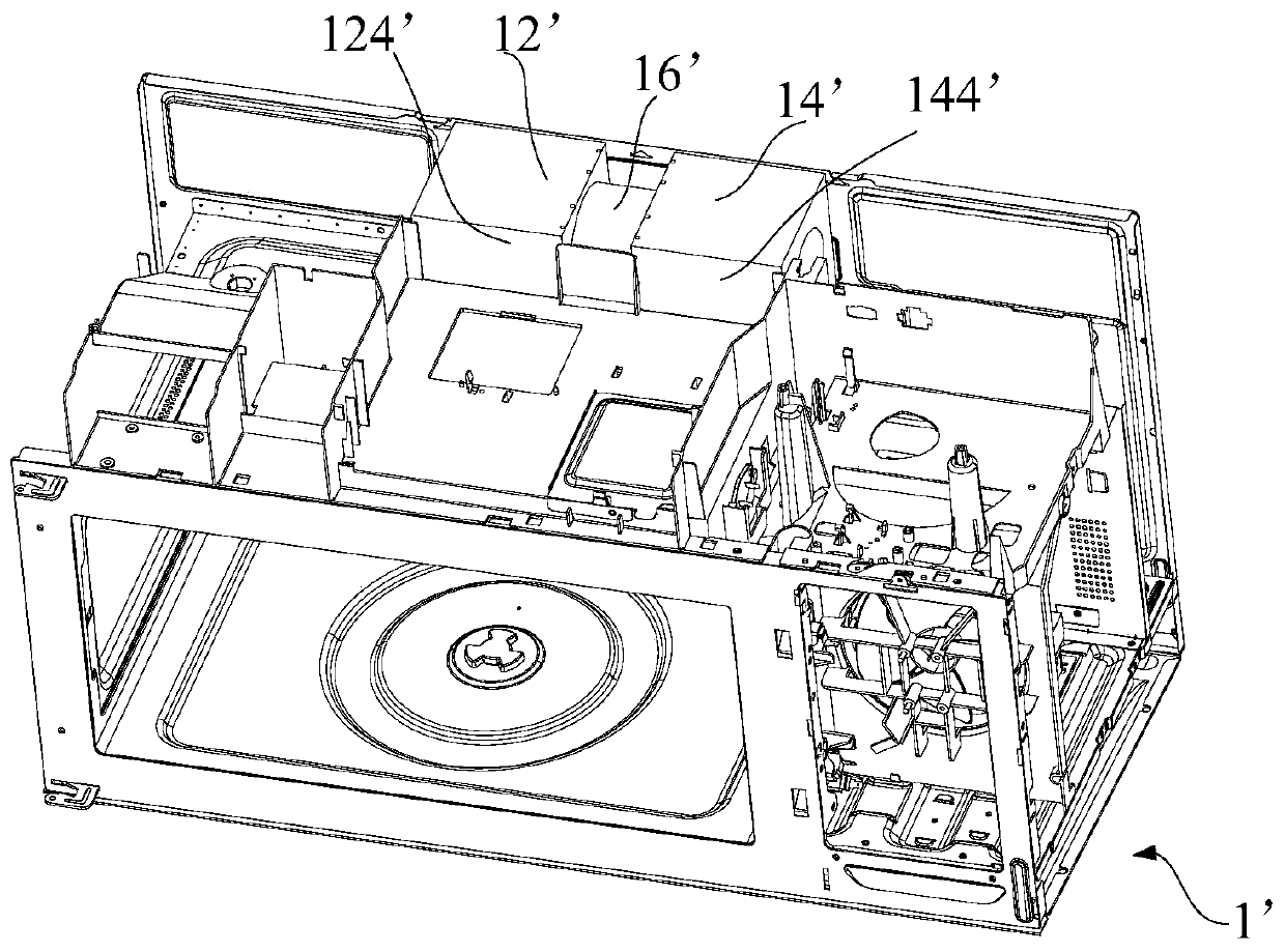
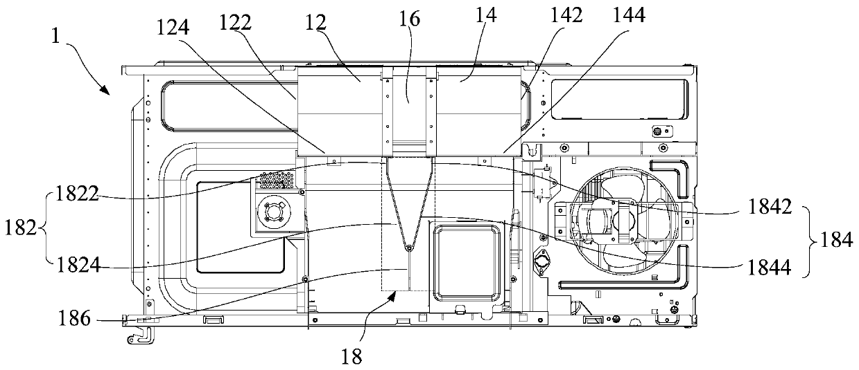
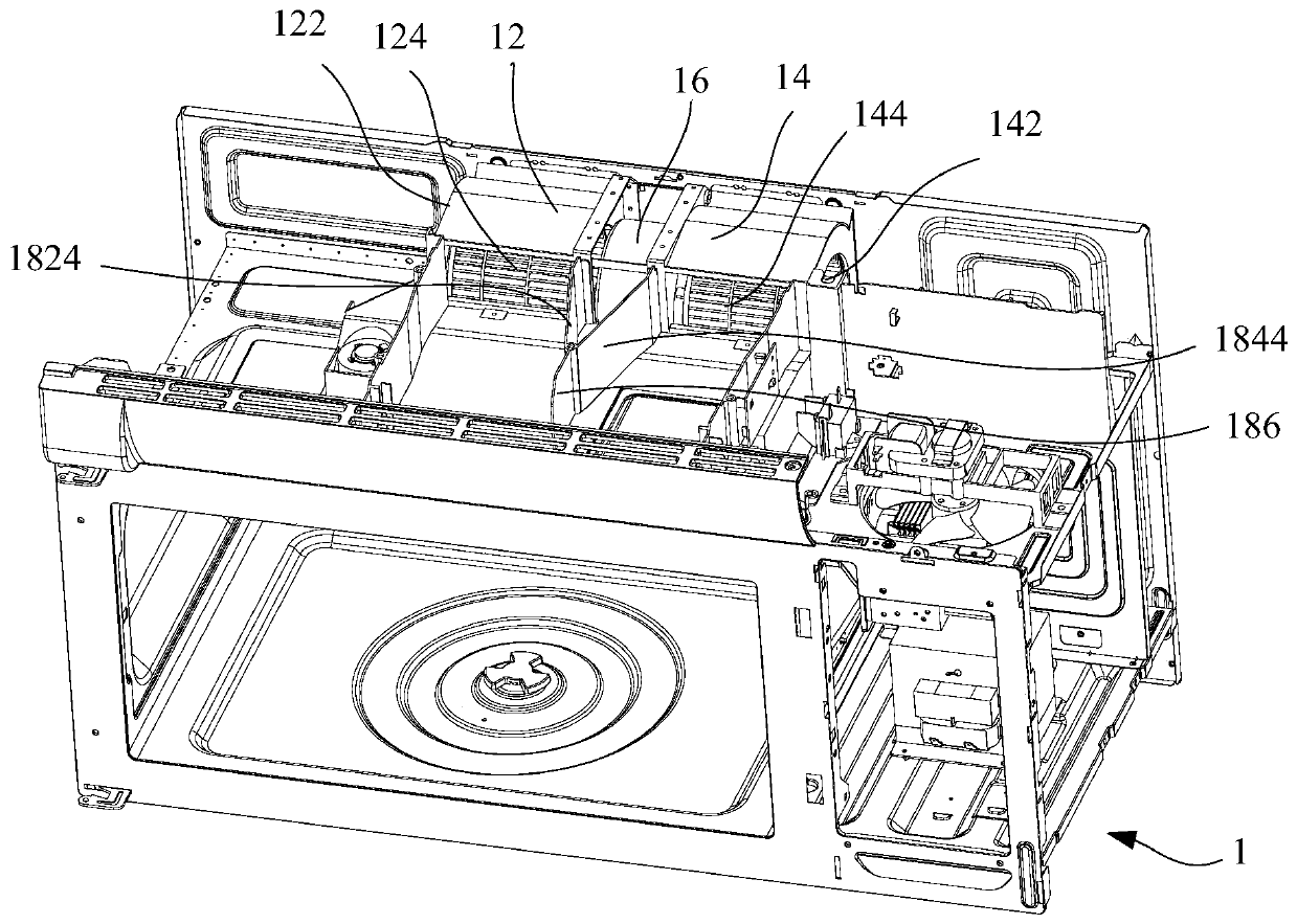
[0040] Refer below Figure 2 to Figure 4 An OTR microwave oven 1 according to some embodiments of the invention is described.

[0041] like Figure 2 to Figure 4 As shown, the embodiment of the pr...


PUM


Abstract

The invention provides an OTR microwave oven comprising a first vortex fan, a second vortex fan, an air exhausting duct and air guiding partitioning plates, wherein the first vortex fan and the second vortex fan are arranged coaxially. The first vortex fan and the second vortex fan are provided with a first air emitting and a second air emitting which face the same direction. The air inlet end of the air exhausting duct communicates with the first air emitting and the second air emitting simultaneously. The air guiding partitioning plates are located in the air exhausting duct and comprise the first partitioning plate and the second partitioning plate which are arranged at the ends, adjacent to each other, of the first vortex fan and the second vortex fan correspondingly, and the ends, separately far from the first vortex fan and the second vortex fan, of the first partitioning plate and the second partitioning plate are connected. By arranging the air guiding partitioning plates in the air exhausting duct, air flows of the first air emitting and the second air emitting are separated from one another, the situation that the two streams of high-speed air flows collide directly and violently in the air exhausting duct to produce large noise is avoided, and the using comfort and satisfaction degrees of users are improved.

Description

technical field [0001] The invention relates to the field of household appliances, in particular to an OTR microwave oven. Background technique [0002] OTR (over the range, located above the stove) microwave oven refers to a microwave oven with the function of a range hood. It is generally hung above the stove and can absorb the smoke and water vapor generated by the stove below during the heating process; There is a fan used to absorb oily fumes in the middle. At the maximum speed, the noise generated by the fan can reach 62-65DB, which will bring troubles to consumers. [0003] like figure 1 As shown, the fan structure of the OTR microwave oven 1' in the related art generally includes a motor 16' arranged in the middle and a first vortex fan 12' and a second vortex fan 14' arranged on both sides. The axial suction of the vortex fan is exhausted along the radial direction of the vortex fan; since the vortex fans on the left and right sides are all driven by the motor 16'...

Claims


Application Information

Patent Timeline
Patent Type & Authority Patents(China)
IPC IPC(8): F24C7/02F24C15/20
Inventor 朱模潭洪力
Owner GUANGDONG MIDEA KITCHEN APPLIANCES MFG CO LTD
Why Eureka
Try Eureka