Circulating high-temperature drying test box

A high-temperature drying and test chamber technology, which is applied in the direction of removing certain component weighing, measuring devices, instruments, etc., can solve the problem of no circulating air duct and variable frequency fan, low degree of automation, and insufficient data recording function. Strong and other issues

Inactive Publication Date: 2017-08-22
SHANGHAI LINPIN INSTR
View PDF0 Cites 5 Cited by
  • Summary
  • Abstract
  • Description
  • Claims
  • Application Information

AI Technical Summary

Problems solved by technology

[0005] (1) The existing drying equipment does not have an optimized circulating air duct and a variable frequency fan, so the drying uniformity is not very good, and it is not energy-saving;
[0006] (2) The existing drying equipment does not have an adjustable dehumidification outlet and variable frequency dehumidification fan, and its dehumidification effect is not ideal;
[0007] (3) The existing drying equipment is not equipped with a weighing sensor, so the relevant moisture parameters of drying cannot be accurately known;
[0008] (4) The existing drying equipment is not equipped with wind speed sensors, so that the effect and relationship of wind speed on drying cannot be accurately determined;
[0009] (5) The existing drying equipment does not have an adjustable slide to adjust the opening size of the air door, so as to change the wind direction and achieve the best baking effect;
[0010] (6) The existing drying equipment is not equipped with a touch screen controller, its degree of automation is not high, and its data recording function is not strong

Method used


Image

  • Circulating high-temperature drying test box
  • Circulating high-temperature drying test box
  • Circulating high-temperature drying test box

Examples


Embodiment Construction

[0037] Below in conjunction with accompanying drawing, the present invention will be further described as follows:

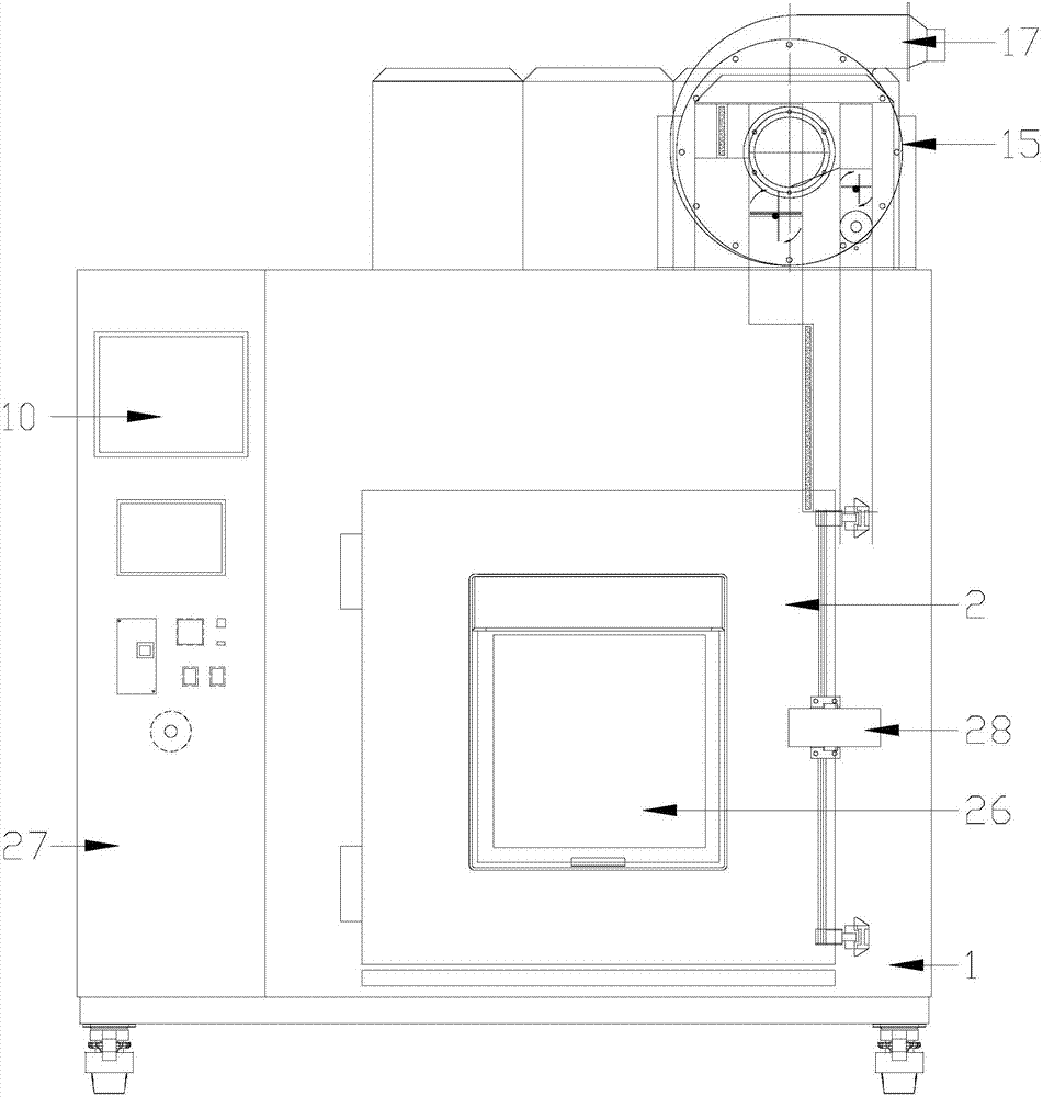
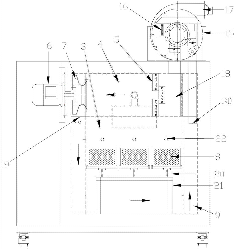
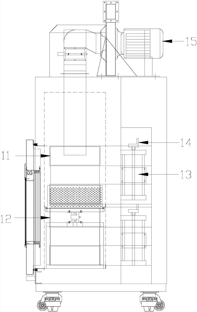
[0038] As shown in the drawings, the present invention includes: a box body 1, a box door 2 is provided on the front surface of the box body 1, and the box door 2 is sealed and connected with the box body 1, and a working chamber 3 and a heating chamber are arranged in the box body 1 4. The heating chamber 4 is set above the working room 3, the heating chamber 4 is equipped with a heater 5, and a frequency conversion fan 6 is installed on one side of the heating chamber 4, and the frequency conversion fan 6 is arranged horizontally, and the frequency conversion fan 6 is installed on the side wall of the box body 1 Above, the output shaft of the frequency conversion fan 6 is equipped with an impeller 7, the impeller 7 is set in the heating chamber 4, a humidification system is installed at the rear of the studio 3, a sample basket 8 is installed at the bottom of t...


PUM


Abstract

The invention relates to a circulating high-temperature drying test box. The circulating high-temperature drying test box comprises a box body, a box door is arranged on the front end surface of the box body, the box door and the box body are connected in a sealing mode, a working chamber and a heating chamber are arranged in the box body, the heating chamber is arranged above the working chamber, a heating device is arranged in the heating chamber, a frequency conversion fan is arranged on one side of the heating chamber, the frequency conversion fan is arranged horizontally, the frequency conversion fan is arranged on the side wall of the box body, an impeller is installed on an output shaft of the frequency conversion fan, the impeller is arranged in the heating chamber, a humidification system is arranged on the rear of the working chamber, a sample basket is arranged at the bottom of the working chamber, two air duct are arranged on the two sides of the left and right side of the working chamber respectively, the working chamber, the heating chamber in the box body and the air ducts on the left and right sides constitute a wind circulation passage, and the heating device and the frequency conversion fan are connected with a controller through lines respectively. According to the circulating high-temperature drying test box, air in the box body can fully flows, the temperature inside the box is ensured to be within a setting range, effects of accurate dehumidification and energy saving and cost reducing are realized, and baked fodder is ensured to be dried faster, better and more uniformly.

Description

[0001] [technical field] [0002] The invention relates to the technical field of environmental test devices, in particular to a circulating high-temperature drying test chamber. [0003] [Background technique] [0004] With the rapid development of human society and the continuous improvement of the degree of industrialization, more and more industrial and agricultural products need to use drying equipment to control the temperature and humidity of the products, such as the drying of feed in agriculture, etc., and at the same time require maximum energy saving Therefore, an automatic equipment that can accurately dry and automatically control temperature and humidity is needed. However, conventional products in the market mostly have the following deficiencies: [0005] (1) The existing drying equipment does not have an optimized circulating air duct and a variable frequency fan, so the drying uniformity is not very good, and it is not energy-saving; [0006] (2) The existin...

Claims


Application Information

Patent Timeline
Patent Type & Authority Applications(China)
IPC IPC(8): G01N5/04
CPCG01N5/045
Inventor 孙光林
Owner SHANGHAI LINPIN INSTR
Why Eureka
Try Eureka