Al technical title is built by PatSnap Al team. It summarizes the technical point description of the patent document.
An optical imaging system and endoscope technology, which is applied in the field of endoscope optical imaging system, can solve the problems that the large field of view optical distortion cannot be well corrected, the optical high-definition imaging, and the relative distortion value are not given.
Active Publication Date: 2017-08-22
EAGLESCOPE MEDICAL TECH CO LTD
View PDF5 Cites 16 Cited by
Summary
Abstract
Description
Claims
Application Information
AI Technical Summary
This helps you quickly interpret patents by identifying the three key elements:
Problems solved by technology
Method used
Benefits of technology
Problems solved by technology
[0003]
Some of the existing endoscope optical systems are composed of plano-concave negative lenses, steering prisms, plano-convex lenses, and follow-up cemented lenses. It optimizes the position of the positive and negative lenses in the objective lens group to correct the distortion of the system, but does not give the achievable Relative distortion value; some are designed with endoscope objective lens made of sapphire material, which is composed of two plano-convex mirrors, and the maximum optical distortion is 20%
[0004]
In summary, the existing endoscopic optical systems cannot correct the optical distortion of the large field of view well and at the same time ensure the optical high-definition imaging in the full field of view
Method used
Image
Click on the blue label to locate the original text in one second.
Reading with bidirectional positioning of images and text.
Examples
Embodiment Construction
[0029] The present invention will be further described below in conjunction with the accompanying drawings and given embodiments, but is not limited thereto.
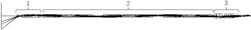
[0030] Such as figure 1 , 2 , 3, 4, 6, 7, and 8, an endoscope optical imaging system includes an objective lens system 1, a relay lens system 2 and an eyepiece system 3 glued together in sequence along the direction of light propagation, and the The relay mirror system 2 is located between the objective lens system 1 and the eyepiece system 3;
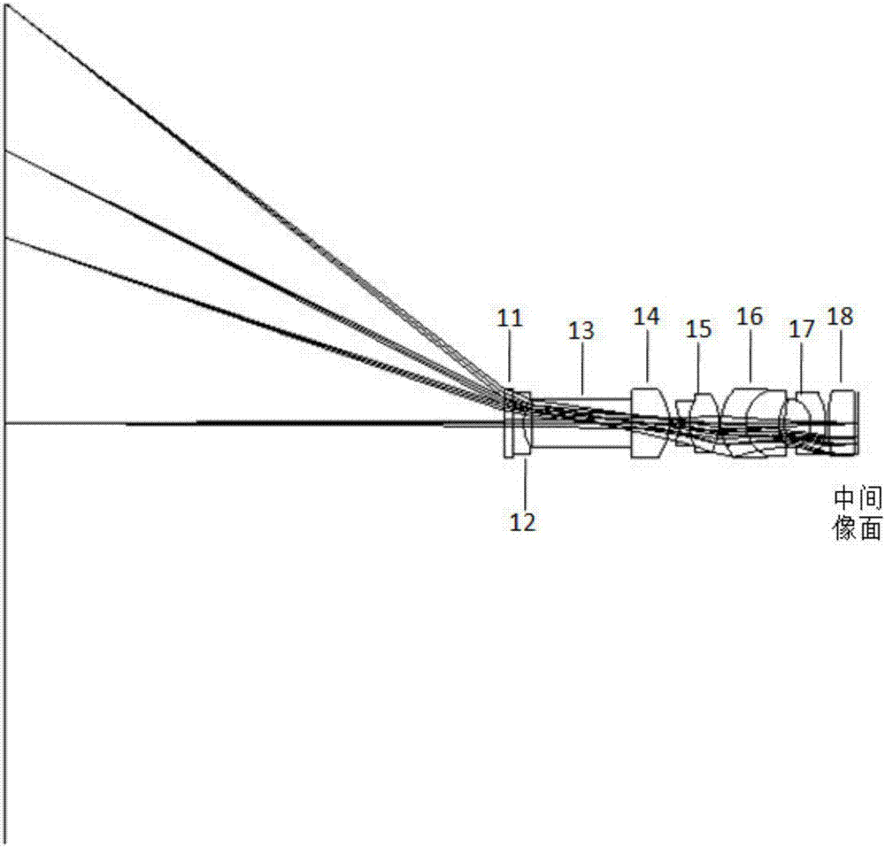
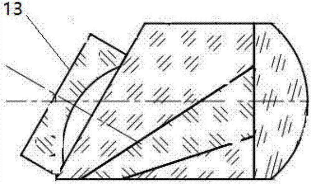
[0031] The objective lens system 1 is an anti-telephoto structure, and the objective lens system 1 includes a first protective window 11, a first plano-concave mirror 12, a turning prism 13, a first plano-convex lens 14, a first double Cemented lens 15, second doublet lens 16, third doublet lens 17 and second plano-convex lens 18;
[0032] The relay mirror system 2 includes n groups of relay mirror groups, and each group of relay mirror groups is a double-telecentric structur...
PUM
Abstract
The invention relates to an optical imaging system of an endoscope. The optical imaging system comprises an objective system, a relay mirror system and an eyepiece system, wherein the objective system, the relay mirror system and the eyepiece system are glued integrally in sequence in the light ray transmission direction; the objective system is an inverted telephoto system, and comprises a first protection window, a first flat concave lens, a deflecting prism, a first flat convex lens, a first two-gluing lens, a second two-gluing lens, a third two-gluing lens and a second flat convex lens, wherein the first protection window, the first flat concave lens, the deflecting prism, the first flat convex lens, the first two-gluing lens, the second two-gluing lens, the third two-gluing lens and the second flat convex lens are glued integrally in sequence in the light ray transmission direction; the relay mirror system comprises n sets of relay mirror sets, each set of relay mirror sets are all of dual-telecentric structures, and the relay mirror sets are constituted by symmetrically arranging two five-glue rod-shaped lens; the eyepiece system is of a telecentric structure, and comprises a first three-gluing lens, a second three-gluing lens, a second convex lens, a second protection window and a second aperture stop, wherein the first three-gluing lens, the second three-gluing lens, the second convex lens, the second protection window and the second aperture stop are glued integrally in sequence in the light ray transmission direction. The optical imaging system of the endoscope has high definition resolution and optical imaging performance with distortion smaller than 5%.
Description
technical field [0001] The invention relates to an optical imaging system, in particular to an endoscope optical imaging system. Background technique [0002] The endoscope is composed of an imaging objective lens at the end, an image relay system at the middle section, and an eyepiece at the proximal end. The imaging objective lens plays a decisive role in the imaging performance of the endoscope. Medical diagnosis and surgery require endoscopes to have the characteristics of large field of view, high resolution, low distortion and small diameter, which puts high demands on the objective lens imaging system and image transfer system of endoscopes. [0003] Some of the existing endoscope optical systems are composed of plano-concave negative lenses, steering prisms, plano-convex lenses, and subsequent cemented lenses. It optimizes the position of the positive and negative lenses in the objective lens group to correct the distortion of the system, but it does not give the ach...
Claims
Application Information
Patent Timeline
Application Date:The date an application was filed.
Publication Date:The date a patent or application was officially published.
First Publication Date:The earliest publication date of a patent with the same application number.
Issue Date:Publication date of the patent grant document.
PCT Entry Date:The Entry date of PCT National Phase.
Estimated Expiry Date:The statutory expiry date of a patent right according to the Patent Law, and it is the longest term of protection that the patent right can achieve without the termination of the patent right due to other reasons(Term extension factor has been taken into account ).
Invalid Date:Actual expiry date is based on effective date or publication date of legal transaction data of invalid patent.