Optical fiber concrete-based picture showing equipment
A concrete and optical fiber technology, which is applied in the field of picture display equipment, can solve the problems of increasing production costs, difficulty in arranging optical fibers regularly, and difficult to realize, and achieves the effect of simplifying production and installation procedures, improving market competitiveness, and saving production costs.
- Summary
- Abstract
- Description
- Claims
- Application Information
AI Technical Summary
Problems solved by technology
Method used
Image
Examples
Embodiment 1
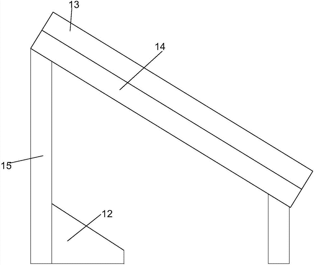
[0047] Such as figure 1 As shown, this embodiment proposes a picture display device based on fiber optic concrete, including:
[0048] A display panel (not shown in the figure), which is made of fiber optic concrete;
[0049] light source 12;
[0050] Drawings (not shown in the figure), which are made of light-transmitting materials, are arranged between the display panel and the light source 12, and are used to print patterns to be displayed; and
[0051] The control circuit (not shown in the figure) includes a controller and a lamp driver, and the controller is electrically connected to the light source 12 through the lamp driver.
[0052] In order to assemble the required size of the display panel conveniently, the display panel is composed of several display units spliced together. Since the display panel is made of fiber optic concrete material, each display unit is also made of fiber optic concrete material, and the side of each display unit must be made of concrete...
Embodiment 2
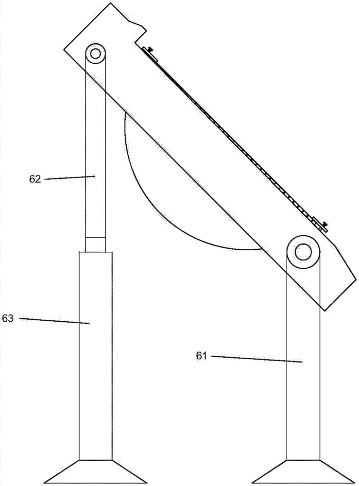
[0055] The difference between the present embodiment and the first embodiment is that, on the basis of the first embodiment, the installation method of each component is changed in this embodiment for the convenience of moving and installing the picture display device based on fiber optic concrete.
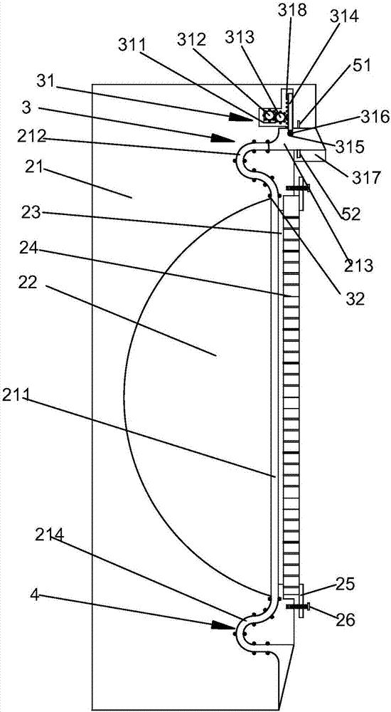
[0056] In this embodiment, the picture display device based on fiber optic concrete also includes: a housing 21, a light source 22 and a control circuit are all arranged in the housing 21, and a transparent sheet 23 located next to the light-emitting surface of the light source 22 is installed on the housing 21. The sheet 23 is made of transparent materials such as glass, which avoids affecting the transmission of light while isolating the display panel 24 and the drawings. A placement channel 211 for inserting the drawings is formed between the transparent sheet 23 and the light emitting surface of the light source 22. The surface away from the light source 22 is formed with a board...
Embodiment 3
[0058] The difference between this embodiment and Embodiment 2 is that in order to ensure that the drawing is not hindered after the end face of the housing 21 facing away from the display panel 24 is installed on the wall or the like, the paper feeding channel, placement The channel 211 and the paper output channel, and the roll-in mechanism and the roll-out mechanism are designed to ensure that the drawings move in the paper feed channel, the placement channel 211 and the paper output channel.
[0059] Specifically, such as figure 2 As shown, the housing 21 is provided with a paper feed passage communicating with one end of the placement passage 211, and the housing 21 is provided with a paper output passage communicating with the other end of the placement passage 211. One end has been placed into the drawing-in mechanism 3 in the entrance of the paper-in passage, and the paper-out passage 214 is provided with a roll-out mechanism 4 for rolling out the drawings located in ...
PUM
 Abstract
Description
Claims
Application Information
 - R&D
- Intellectual Property
- Life Sciences
- Materials
- Tech Scout
- Unparalleled Data Quality
- Higher Quality Content
- 60% Fewer Hallucinations
Browse by: Latest US Patents, China's latest patents, Technical Efficacy Thesaurus, Application Domain, Technology Topic, Popular Technical Reports.
© 2025 PatSnap. All rights reserved.Legal|Privacy policy|Modern Slavery Act Transparency Statement|Sitemap|About US| Contact US: help@patsnap.com


