Eureka AIR delivers breakthrough ideas for toughest innovation challenges, trusted by R&D personnel around the world.

Switch cabinet and pressure relief structure thereof

A technology of pressure relief structure and switchgear, applied in the direction of switchgear, switchgear setting, substation/switch layout details, etc., can solve hidden dangers, safety problems of pressure relief structure, etc., reduce impact force and solve safety hazards Effect

Active Publication Date: 2017-08-22
TIANJIN PINGGAO INTELLIGENT ELECTRIC +2
View PDF6 Cites 10 Cited by
  • Summary
  • Abstract
  • Description
  • Claims
  • Application Information

AI Technical Summary

Problems solved by technology

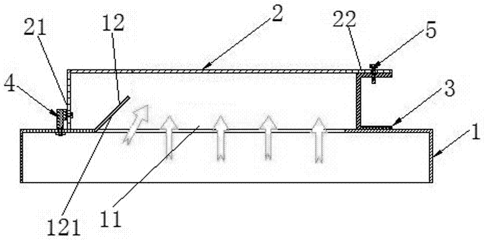
[0005] The purpose of the present invention is to provide a switchgear pressure relief structure to solve the problem of potential safety hazards in the current pressure relief structure; in addition, the purpose of the present invention is to provide a switchgear using the above pressure relief structure

Method used


Image

  • Switch cabinet and pressure relief structure thereof
  • Switch cabinet and pressure relief structure thereof
  • Switch cabinet and pressure relief structure thereof

Examples


Embodiment 2

[0040] The specific embodiment 2 of the switch cabinet of the present invention, the difference between the switch cabinet in this embodiment and the switch cabinet described in the specific embodiment 1 of the above-mentioned switch cabinet is only: as Figure 8 As shown, in this embodiment, the pressure relief structure includes a guide part 6, and the guide part 6 includes a fixed part 61 and a guide plate 62 fixed on the top board of the cabinet, and the fixed part 61 and the hinge 204 are fixed on the top board 201 of the cabinet , the guide surface 2121 is disposed on the guide plate 62, and the structure of the guide plate 62 is the same as that of the guide plate described in the specific embodiment of the switchgear above, and will not be repeated here.

specific Embodiment 3

[0041] The specific embodiment 3 of the switchgear of the present invention, the difference between the switchgear in this embodiment and the specific embodiment 2 of the above-mentioned switchgear is only that a hinge shaft is provided on the guide part, and the pressure relief plate is directly hinged on the hinge shaft of the guide part superior.

specific Embodiment 4

[0042] The specific embodiment 4 of the switch cabinet of the present invention, the difference between the switch cabinet in this embodiment and the specific embodiment 1 of the above-mentioned switch cabinet is only that the pressure relief plate of the pressure relief structure in this embodiment is a flat plate, and the top plate of the cabinet body A groove is provided, the pressure relief port is arranged in the groove, the guide plate is also arranged in the groove, and the pressure relief plate covers the notch of the groove.


PUM


Abstract

The invention relates to the field of switchgear, in particular to a switch cabinet and a pressure relief structure thereof. The switch cabinet comprises a cabinet body, wherein the cabinet body is provided with a pressure relief port, the pressure relief port is provided with pressure relief plates, each pressure relief plate comprises a pressure relief connection part and a maintaining connection part which is used for enabling the corresponding pressure relief plate to be connected on the cabinet body always, and the pressure relief port is provided with a foldable sheltering plate which is positioned on one side, facing the pressure relief port, of the pressure relief plate and used for sheltering one side, close to the maintaining connection part, of the pressure relief port; or the pressure relief port is provided with a guide plate positioned on one side, facing the pressure relief port, of the pressure relief plate, and the guide plate is provided with a guide surface which is used for guiding arcing energy inside the cabinet body to a region, far away from the maintaining connection part, on each pressure relief plate; or, a distance between the pressure relief connection part and the pressure relief port is less than a distance between the maintaining connection part and the pressure relief port, so that the pressure relief port is arranged eccentrically relative to the pressure relief plates, thereby solving the problem that potential safety hazards exist in the existing pressure relief structure.

Description

technical field [0001] The invention relates to the field of switch equipment, in particular to a switch cabinet and a pressure relief structure thereof. Background technique [0002] The arc effects generated during the burning of the arc fault inside the switchgear include pressure effects, thermal effects, radiation and acoustic effects. These arcing effects are powerful and will damage switchgear and cause injury to nearby workers. Various switchgear manufacturers have adopted various measures to strengthen the switchgear to protect the switchgear from arcing faults. In addition to strictly ensuring the manufacturing quality of the switchgear, performing correct maintenance and operating accidents in accordance with relevant regulations, it is also necessary to design and configure fast-acting pressure relief structure, once an internal arcing fault occurs. In addition to strictly ensuring the manufacturing quality of the switchgear and performing correct maintenance a...

Claims


Application Information

Patent Timeline
Patent Type & Authority Applications(China)
IPC IPC(8): H02B13/025H02B1/30
CPCH02B1/306H02B13/025
Inventor 张罗锐陈利民丛艳伟张聚会崔秋莲
Owner TIANJIN PINGGAO INTELLIGENT ELECTRIC
Why Eureka
Eureka Blog
Learn More