Hybrid direct current station control coordination control method and device and power transmission system
A technology of coordinated control and hybrid DC, applied in the direction of reducing/preventing power oscillation, which can solve problems such as inability to allocate a reasonable amount of power modulation
Pending Publication Date: 2017-08-22
CHINA SOUTH POWER GRID ELECTRIC POWER RES INST
0 Cites 7 Cited by
AI-Extracted Technical Summary
Problems solved by technology
[0005] Embodiments of the present invention provide a coordinated control method, device, and power transmission system for hybrid DC station control, which solves the problem that the DC power transmission system using the frequency co...
Method used
Finally, the coordinated control device obtains the power modulation amount according to the frequency control and power distribution control of the AC system at the sending end, and corrects the active power of the flexible direct current; whether the active power of the two receiving end flexible direct currents is judged by the power transfer control If the maximum active power is exceeded, the power transfer will be performed, and finally the final flexible DC power will be obtained and sent to their respective extreme control layers to realize the rapid adjustment of the respective active power of the hybrid multi-terminal DC, thereby ensuring the effect of frequency stability.
In actual application, the process frequency control of generating the power adjustment amount usually will be based on the difference between the preset frequency of the conventional direct current sending end and the current frequency of the conventional direct current sending end; the power adjustment amount will be filtered to obtain the first flexible direct current The first adjustment amount of the receiving end, and generate the second adjustment amount of the second flexible DC re...
Abstract
The embodiment of the invention provides a hybrid direct current station control coordination control method and device and a power transmission system, and relates to the technical field of alternate current and direct current power transmission system transient stability control. The method, the device and the power transmission system solve the problems that the frequency stabilizing effect of each receiving end can not be ensured and the reasonable power modulation rate can not be allocated according to the actual situation of each receiving end in the prior art when a direct current power transmission system adopting a frequency control method is used for frequency stabilization. The method includes the steps that the difference of a preset frequency of a conventional direct current sending end and the current frequency of the conventional direct current sending end is obtained; according to the difference, the power modulation rate is generated, filtering is conducted on the power modulation rate to obtain a first modulation rate of a first flexible direct current receiving end, and a second modulation rate of a second flexible direct current receiving end is generated through the subtraction; according to the first modulation rate, the active power of the first flexible direct current receiving end is corrected, and according to the second modulation rate, the active power of the second flexible direct current receiving end is corrected. The method, the device and the power transmission system are used for hybrid direct current station control coordination control.
Application Domain
Power oscillations reduction/prevention
Technology Topic
Electric power transmissionFrequency stabilization +6
Image
Examples
- Experimental program(3)
Example Embodiment
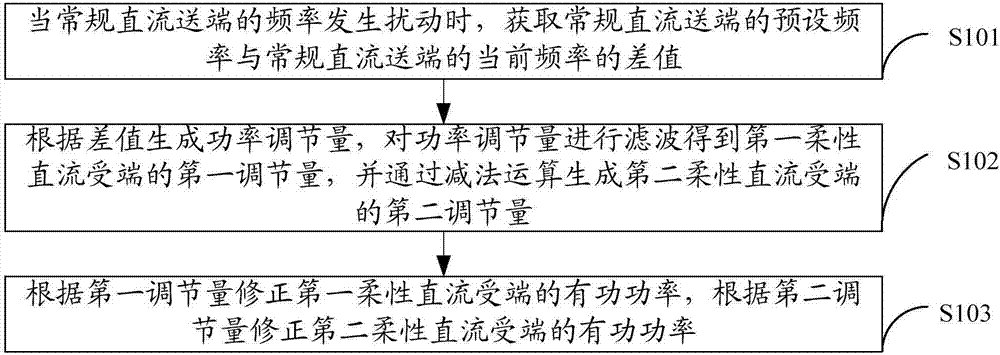
[0028] Embodiment 1. The embodiment of the present invention provides a coordinated control method for hybrid DC station control, such as figure 1 Shown include:
[0029] S101: When the frequency of the conventional DC transmission terminal is disturbed, obtain the difference between the preset frequency of the conventional DC transmission terminal and the current frequency of the conventional DC transmission terminal.
[0030] S102. Generate a power adjustment amount according to the difference, filter the power adjustment amount to obtain the first adjustment amount of the first DC flexible receiving end, and generate a second adjustment amount of the second DC flexible receiving end through subtraction, where the second adjustment amount is equal to The power adjustment amount minus the first adjustment amount.
[0031] It should be noted that the first adjustment amount may be equal to the second adjustment amount or the first adjustment amount may be different from the first adjustment amount.
[0032] S103. Correct the active power of the first DC flexible receiving end according to the first adjustment amount, and correct the active power of the second DC flexible receiving end according to the second adjustment amount.
[0033] Optionally, the method further includes: obtaining the total active power of the hybrid DC transmission system; distributing the total active power into the active power of the first flexible DC receiving end and the active power of the second flexible DC receiving end; wherein the total active power is equal to the first The sum of the active power of a flexible DC receiving terminal and the active power of a second flexible DC receiving terminal.
[0034] It should be noted that the total active power can be obtained through the operation plan set by the dispatcher or the power set by the operator; in practical applications, the total active power is usually allocated to the first active power of the first flexible DC receiving end The step of connecting with the second active power of the second flexible DC receiving end is called the receiving end power distribution link; this link provides a variety of distribution methods, such as proportional distribution method, capacity distribution method, etc., the total active power is calculated to obtain the first The first active power of a flexible DC receiving terminal and the second active power of a second flexible DC receiving terminal.
[0035] In practical applications, the frequency control of the process of generating the power adjustment value is usually based on the difference between the preset frequency of the conventional DC transmission end and the current frequency of the conventional DC transmission end; the power adjustment value is filtered to obtain the first flexible DC receiving end One adjustment quantity, and the second adjustment quantity of the second flexible DC receiving end is generated by subtraction, where the second adjustment quantity is equal to the power adjustment quantity minus the first adjustment quantity. This process is called power distribution control (also known as low-pass based Filtering power distribution control, specific filtering can be achieved by a first-order low-pass filter, and subtraction can be achieved by a subtractor); for example, the power modulation amount generated by frequency control is filtered through the receiving end power distribution link, thereby The first active power of the first DC flexible receiving terminal is generated, and the second active power of the second DC flexible receiving terminal is obtained through subtraction operation; thereby realizing the slow response of the weak receiving terminal AC system power regulation and the strong receiving terminal AC system power regulation Fast response.
[0036] Specifically, frequency control includes the following steps:
[0037] 1. Filter the difference between the preset frequency of the conventional DC transmission terminal and the current frequency of the conventional DC transmission terminal to eliminate glitch signals (usually filter the difference between the preset frequency of the conventional DC transmission terminal and the current frequency of the conventional DC transmission terminal to eliminate This process of glitch signal is called filtering link).
[0038] 2. Compare the difference between the frequency of the eliminated glitch signal with the frequency setting value (usually the process of comparing the difference between the frequency of the eliminated glitch signal with the frequency setting value is called the dead zone link); What is, when the frequency difference of the eliminated glitch signal is less than the set value of the frequency, no action is taken; specifically, the dead zone means that when the frequency deviation signal is less than the set value of the dead zone, the output of the dead zone link is 0 ; When the frequency deviation signal is greater than the set value of the dead zone, the output of the dead zone link is the frequency deviation, and its main function is to prevent frequent actions of the frequency controller.
[0039] 3. When the frequency difference is greater than or equal to the frequency setting value of the dead zone, the control deviation is formed according to the difference between the setting value and the frequency, and the ratio of the deviation (English full name: Proportion, abbreviation: P) and integral (English Full name: Integral, abbreviation: I) constitute the control variable by linear combination (usually the control deviation is constituted by the difference between the set value and the frequency, and the proportional (P) and integral (I) of the deviation are constituted by the linear combination of the control variable. The process is called the PI link); specifically, the PI link can be executed through the PI controller.
[0040] 4. Limit the output control quantity and output the total power modulation quantity (usually the process of limiting the output control quantity and outputting the total power modulation quantity is called the output limit link).
[0041] Specifically, the power allocation control includes the following steps:
[0042] 1. Perform low-pass filtering of the total power modulation with a large time constant to obtain the first power adjustment generated by the weak receiving end flexible DC frequency control (usually, the total power modulation is subjected to low-pass filtering with a large time constant to obtain The process of the first power adjustment amount generated by the weak receiving end flexible DC frequency control is called the low-pass filtering link).
[0043] 2. Subtract the first power adjustment amount of the weak receiving end flexible DC from the total power adjustment amount to obtain the second power adjustment amount of the strong receiving end flexible DC.
[0044] 3. Superimpose the first power adjustment amount on the active power of the first DC flexible receiving terminal, and superimpose the second power adjustment amount on the active power of the second DC flexible DC receiving terminal to realize the final frequency stability control.
[0045] Optionally, the method further includes: when the corrected active power of the first DC flexible receiving terminal is greater than or equal to the maximum active power of the first DC flexible receiving terminal, transferring the excess active power of the first DC flexible receiving terminal to the second The flexible DC receiving terminal generates the redistributed active power of the first DC flexible receiving terminal and the active power of the second DC flexible receiving terminal; the expression formula of the active power exceeding the first DC flexible receiving terminal is: M1=P1+△1- N1; M1 represents the excess active power of the first DC flexible receiving terminal, P1 represents the active power of the first DC flexible receiving terminal, Δ1 represents the first adjustment amount, and N1 represents the maximum active power of the first DC flexible receiving terminal.
[0046] Optionally, the method further includes: when the corrected active power of the second DC flexible receiving terminal is greater than or equal to the maximum active power of the second DC flexible receiving terminal, transferring the excess active power of the second DC flexible receiving terminal to the first The flexible DC receiving terminal generates the redistributed active power of the first DC flexible receiving terminal and the active power of the second DC flexible receiving terminal; the expression formula for the excess active power of the second DC flexible receiving terminal is: M2 = P2 + △2- N2; M2 represents the excess active power of the second DC flexible receiving terminal, P2 represents the active power of the second DC flexible receiving terminal, Δ2 represents the second adjustment amount, and N2 represents the maximum active power of the second DC flexible receiving terminal.
[0047] It should be noted that in actual applications, when the corrected active power of the first DC flexible receiving terminal is greater than or equal to the maximum active power of the first DC flexible receiving terminal, the excess active power of the first DC flexible receiving terminal is transferred to The second DC flexible receiving terminal or when the corrected active power of the second DC flexible receiving terminal is greater than or equal to the maximum active power of the second DC flexible receiving terminal, the excess active power of the second DC flexible receiving terminal is transferred to the first DC flexible receiving terminal The process of receiving end is called power transfer control; the process of performing power transfer control is to prevent the first flexible DC receiving end or the second flexible DC receiving end from exceeding the first flexible DC receiving end's active power due to the corrected active power of the first flexible DC receiving end. The maximum active power of the DC receiving terminal itself or the corrected active power of the second DC flexible receiving terminal exceeds the maximum active power of the second DC flexible receiving terminal itself, causing the first or second DC flexible receiving terminal to be in an overload state , Causing safety hazards.
[0048] The coordinated control method for hybrid DC station control provided by the embodiment of the present invention filters the power adjustment amount generated by the frequency difference of the conventional DC transmission end when the frequency of the conventional DC transmission end is disturbed to obtain the first adjustment of the first flexible DC receiving end The second adjustment value of the second DC flexible receiving end is generated by subtraction; unlike the prior art, the power adjustment amount generated directly according to the frequency difference of the conventional DC transmission end is used to correct the first flexible DC receiving end and the second For the flexible DC receiving terminal, since the possible difference between the first flexible DC receiving terminal and the second flexible DC receiving terminal is considered, the first adjustment value is used for the first flexible DC receiving terminal to correct the second flexible DC receiving terminal. The second adjustment value is used for correction, thereby ensuring the frequency stabilization effect of each receiving end; it solves the problem that the DC transmission system adopting the frequency control method in the prior art cannot allocate reasonably according to the actual situation of each receiving end when the frequency is stabilized. The amount of power modulation to ensure the stability of the frequency of each receiving end.
Example Embodiment
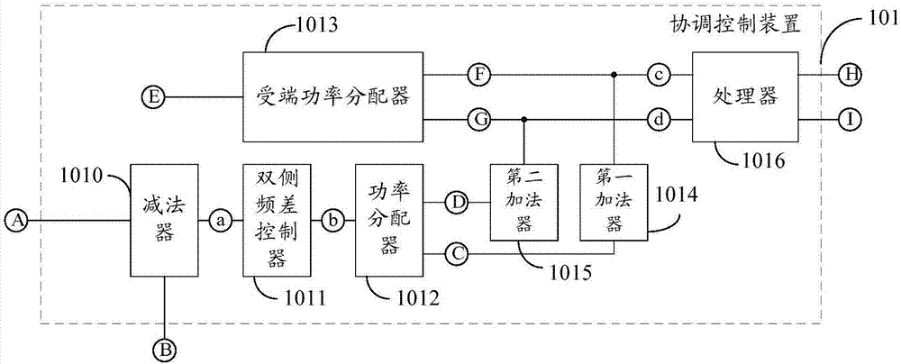
[0049] Embodiment 2. The embodiment of the present invention provides a coordinated control device 101 for hybrid DC station control, such as figure 2 Shown include:
[0050] The subtractor 1010, the first node a, the first signal input terminal A and the second signal input terminal B connected to the subtractor 1010, the double-sided frequency difference controller 1011 connected to the first node a, and the double-sided frequency difference control The second node b connected to the second node b, the power divider 1012 connected to the second node b, the first signal output terminal C and the second signal output terminal D connected to the power divider 1012; the subtractor 1010 is used for conventional When the frequency of the DC transmission terminal is disturbed, the difference between the preset frequency of the conventional DC transmission terminal and the current frequency of the conventional DC transmission terminal is obtained; a double-sided frequency difference controller 1011 is used to generate the power adjustment value according to the difference obtained by the subtractor; The distributor 1012 is used to filter the power adjustment amount generated by the double-sided frequency difference controller to obtain the first adjustment amount of the first DC flexible receiving end, and generate the second adjustment amount of the second DC flexible receiving end through subtraction. The second adjustment amount is equal to the power adjustment amount minus the first adjustment amount, the active power of the first DC flexible receiving end is corrected according to the first adjustment amount, and the active power of the second DC flexible receiving end is corrected according to the second adjustment amount.
[0051] Optionally, the coordination control device 101 further includes: a receiving end power distributor 1013, a third signal input end E, a third signal output end F, and a fourth signal output end G connected to the receiving end power distributor 1013, and The first adder 1014 connected to the three-signal output terminal F, the first signal output terminal C and the third node c connected to the first adder 1014, the second adder 1015 connected to the fourth signal output terminal G, and the The second signal output terminal D and the fourth node d connected to the two adder 1015; the receiving end power distributor 1013 is also used to obtain the total active power of the hybrid DC transmission system; the receiving end power distributor 1013 is also used to The active power is divided into the active power of the first DC flexible receiving terminal and the active power of the second DC flexible receiving terminal; the total active power is equal to the sum of the active power of the first DC flexible receiving terminal and the active power of the second DC flexible receiving terminal.
[0052] Optionally, the coordination control device 10 further includes: a processor 1016; a third node c, a fourth node d, a fifth signal output terminal H, and a sixth signal output terminal I connected to the processor 1016; the processor 1016 uses When the active power of the first DC flexible receiving terminal corrected by the first adder 1014 is greater than or equal to the maximum active power of the first DC flexible receiving terminal, the active power exceeding the first DC flexible receiving terminal is transferred to the second DC flexible receiving terminal. The active power of the first DC flexible receiving terminal and the active power of the second DC flexible receiving terminal are generated. The expression formula for the excess active power of the first DC flexible receiving terminal is: M1=P1+△1-N1; M1 Indicates the excess active power of the first DC flexible receiving terminal, P1 indicates the active power of the first DC flexible receiving terminal, Δ1 indicates the first adjustment amount, and N1 indicates the maximum active power of the first DC flexible receiving terminal.
[0053] Optionally, the coordination control device 10 further includes: a processor 1016; a third node c, a fourth node d, a fifth signal output terminal H, and a sixth signal output terminal I connected to the processor 1016; the processor 1016 uses When the active power of the second DC flexible receiving terminal corrected by the second adder 1015 is greater than or equal to the maximum active power of the second DC flexible receiving terminal, the excess active power of the second DC flexible receiving terminal is transferred to the first DC flexible receiving terminal. The real power of the first DC flexible receiving terminal and the active power of the second DC flexible receiving terminal are generated; the expression formula for the excess active power of the second DC flexible receiving terminal is: M1=P2+△2-N2; M2 Indicates the excess active power of the second DC flexible receiving terminal, P2 indicates the active power of the second DC flexible receiving terminal, Δ2 indicates the second adjustment amount, and N2 indicates the maximum active power of the second DC flexible receiving terminal.
[0054] In the coordinated control of the hybrid DC station control provided by the embodiment of the present invention, when the frequency of the conventional DC transmission end is disturbed, the power adjustment amount generated by the frequency difference of the conventional DC transmission end is filtered to obtain the first adjustment of the first flexible DC receiving end The second adjustment value of the second DC flexible receiving end is generated by subtraction; unlike the prior art, the power adjustment amount generated directly according to the frequency difference of the conventional DC transmission end is used to correct the first flexible DC receiving end and the second For the flexible DC receiving terminal, since the possible difference between the first flexible DC receiving terminal and the second flexible DC receiving terminal is considered, the first adjustment value is used for the first flexible DC receiving terminal to correct the second flexible DC receiving terminal. The second adjustment value is used for correction, thereby ensuring the frequency stabilization effect of each receiving end; it solves the problem that the DC transmission system adopting the frequency control method in the prior art cannot allocate reasonably according to the actual situation of each receiving end when the frequency is stabilized. The amount of power modulation to ensure the stability of the frequency of each receiving end.
Example Embodiment
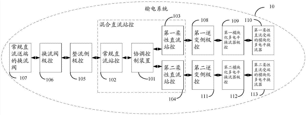
[0055] Embodiment 3. The embodiment of the present invention provides a power transmission system 10, including: any one of the coordinated control device 1011 for hybrid DC station control as provided in the second embodiment, connected to the coordinated control device 1011 for hybrid DC station control Conventional DC station control 102, first flexible DC station control 103 and second flexible DC station control 104, rectifier side pole control 105 connected to conventional DC station control 102, converter valve pole control 106 connected to rectifier side pole control 105 , The converter valve 107 of the conventional DC sending end connected to the converter valve pole control 106, the first inverter side pole control 108 connected to the first flexible DC station control 103, and the first inverter side pole control 108 connected to the first inverter side pole control 108 A modular multilevel converter pole control 109, the first flexible DC receiving end modular multilevel converter 110 connected to the first modular multilevel converter pole control 109, and the second flexible DC The second inverter side pole control 111 connected to the station control 104, the second modular multilevel converter pole control 112 connected to the second inverter side pole control 111, and the second modular multilevel converter The modular multi-level converter 113 of the second flexible DC receiving end connected to the pole control 112.
[0056] It should be noted, Figure 4-a Schematic diagram of the three-terminal hybrid DC transmission system structure, Figure 4-b Schematic diagram of the three-terminal hybrid DC control layer structure, Figure 4-c for Figure 4-b The control diagram of the coordinated control device in the middle, Figure 4-d for Figure 4-c Control schematic diagram of medium frequency control; among them, Figure 4-b China modular multilevel converter (full English name: Modular MultilevelConverter, abbreviation: MMC), Figure 4-c The middle coordinated control device includes the receiving end power distribution link, frequency control and power transfer control. The coordinated control device firstly sets the power reference value P according to the scheduling plan Or the power reference value P given by the operator set Determine the total active power reference value P of the three-terminal hybrid DC transmission system in; The second step, through the receiving end power distribution such as proportional distribution mode to P in Decompose and obtain the active power reference value P of two flexible DC MMC1_ref1 , P MMC2_ref1; The third step is to control the frequency according to the sending end system frequency reference f ref And frequency measurement f mes Calculate the power adjustment amount P FLC , The power adjustment amount is distributed based on filtering, and the respective power adjustment amount P of the flexible DC is obtained MMC1_FLC With P MMC2_FLC; Superimpose the power adjustment value on the original power reference value to get P MMC1_ref2 , P MMC2_ref2; Finally, according to the capacity limit of the flexible DC, calculate the power transfer value and get the final reference value P MMC1_ref3 , P MMC2_ref3.
[0057] Figure 4-d The middle coordinated control device improves the original frequency control by adding filter-based power distribution control. The original frequency control includes the measurement filter link (the time constant is small), the dead zone link, the proportional integral control link and the output limiting link. Figure 4-d Where T is the time constant of the measurement link, generally a smaller value, s is the differential operator, f ref Is the sender frequency reference value, f mes Is the frequency measurement value, k p , K i It is the proportional coefficient and integral coefficient of PI control. The frequency deviation signal passes through the measurement filtering link to obtain the frequency deviation signal used for calculation. It first passes through the dead zone link. If the frequency difference is less than the dead zone, the frequency control does not start; if the frequency difference is greater than the dead zone Zone, the frequency control starts. After the frequency control is started, the frequency deviation is first processed by PI control, and the result obtained is passed through the output limiting link to obtain the power adjustment amount P along with the frequency control. FLC. Then, the power distribution control uses a first-order low-pass filter (where T MMC1 In order to allocate the control time constant, generally take a larger value) The slowly fluctuating component of the power modulation is used as the power modulation P of the flexible DC 1 MMC1_FLC , And then by the total modulation amount P FLC Subtract P MMC1_FLC Obtain the relatively fast fluctuating flexible DC power modulation quantity P MMC2_FLC; Exemplarily take two flexible DC receiving ends with the same capacity of 2500Mw and a total power of 5000MW as an example. If the frequency deviation is 2Hz, after frequency control, P MMC1_FLC Can be 50MW, P MMC2_FLC It can be 150MW; then, the active power of the first flexible DC receiving end is 2500+50=2550MW, and the active power of the second flexible DC receiving end is 2500+150=2650MW.
[0058] Finally, the coordinated control device obtains the power modulation amount according to the frequency control and power distribution control of the sending end AC system, and corrects the active power of the flexible DC; power transfer control determines whether the active power of the two receiving end flexible DC exceeds its maximum If the active power is exceeded, power transfer is performed, and the final flexible DC power is finally obtained and sent to its respective pole control layer to achieve rapid adjustment of the respective active power of hybrid multi-terminal DC, thereby ensuring the effect of frequency stability.
[0059] In the hybrid DC station-controlled power supply system provided by the embodiment of the present invention, when the frequency of the conventional DC transmission end is disturbed, the power adjustment amount generated by the frequency difference of the conventional DC transmission end is filtered to obtain the first adjustment of the first flexible DC receiving end The second adjustment value of the second DC flexible receiving end is generated by subtraction; unlike the prior art, the power adjustment amount generated directly according to the frequency difference of the conventional DC transmission end is used to correct the first flexible DC receiving end and the second For the flexible DC receiving terminal, since the possible difference between the first flexible DC receiving terminal and the second flexible DC receiving terminal is considered, the first adjustment value is used for the first flexible DC receiving terminal to correct the second flexible DC receiving terminal. The second adjustment value is used for correction, thereby ensuring the frequency stabilization effect of each receiving end; it solves the problem that the DC transmission system adopting the frequency control method in the prior art cannot allocate reasonably according to the actual situation of each receiving end when the frequency is stabilized. The amount of power modulation to ensure the stability of the frequency of each receiving end.
PUM


Description & Claims & Application Information
We can also present the details of the Description, Claims and Application information to help users get a comprehensive understanding of the technical details of the patent, such as background art, summary of invention, brief description of drawings, description of embodiments, and other original content. On the other hand, users can also determine the specific scope of protection of the technology through the list of claims; as well as understand the changes in the life cycle of the technology with the presentation of the patent timeline. Login to view more.