Knob wire controller and control method thereof as well as electrical equipment

A technology of knob wire controller and control method, which is applied in the direction of electrical components, electronic switches, pulse technology, etc., and can solve the problem of high cost of touch screen wire controller

Pending Publication Date: 2017-08-22
GREE ELECTRIC APPLIANCES INC
View PDF7 Cites 7 Cited by
  • Summary
  • Abstract
  • Description
  • Claims
  • Application Information

AI Technical Summary

Problems solved by technology

[0004] Embodiments of the present invention provide a knob wire controller and its control method and electrical equipment, so as to at least solve the technical problem of high cost of light touch button wire controllers or touch screen wire controllers in the prior art

Method used


Image

  • Knob wire controller and control method thereof as well as electrical equipment
  • Knob wire controller and control method thereof as well as electrical equipment
  • Knob wire controller and control method thereof as well as electrical equipment

Examples


Embodiment 1

[0021] According to an embodiment of the present invention, an embodiment of a control method of a rotary knob wire controller is provided. It should be noted that the steps shown in the flow charts of the accompanying drawings can be executed in a computer system such as a set of computer-executable instructions , and, although a logical order is shown in the flowcharts, in some cases the steps shown or described may be performed in an order different from that shown or described herein.

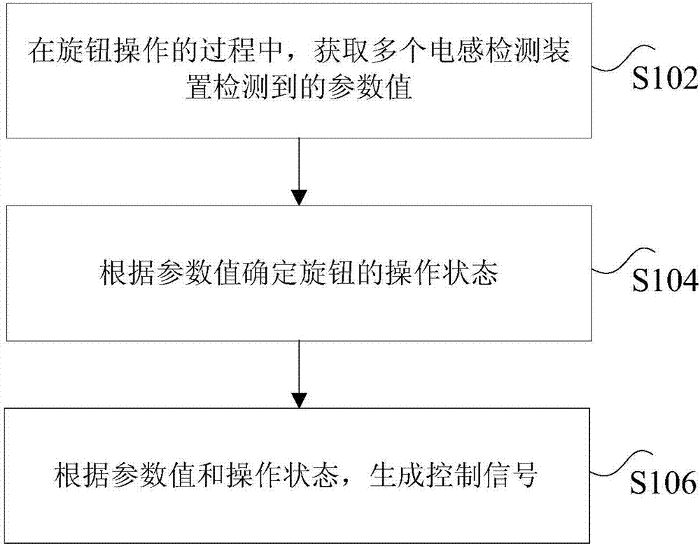
[0022] figure 1 It is a flow chart of a control method of a knob wire controller according to an embodiment of the present invention, such as figure 1 As shown, the method includes the following steps:

[0023] Step S102, during the operation of the knob, acquire the parameter values ​​detected by a plurality of inductance detection devices.

[0024] Specifically, the above parameter values ​​may include: a mutual inductance parameter value and an inductance parameter value.

[0025] In ...

Embodiment 2

[0052] According to an embodiment of the present invention, an embodiment of a knob wire controller is provided.

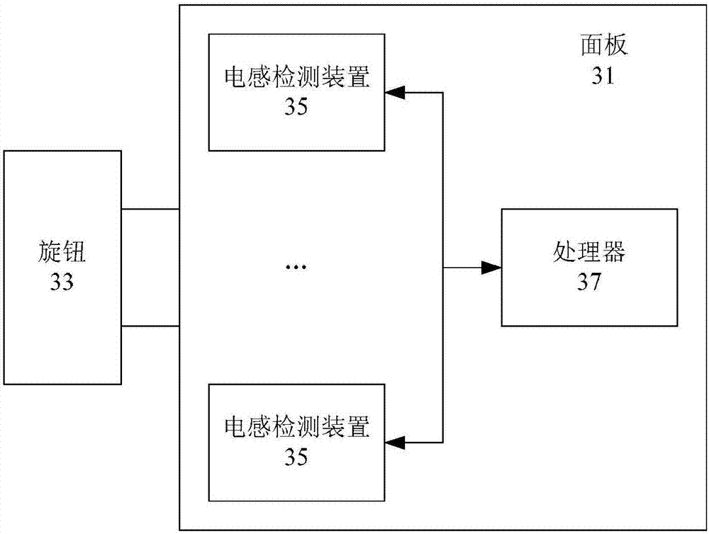
[0053] image 3 is a schematic diagram of a knob wire controller according to an embodiment of the present invention, such as image 3 As shown, the knob wire controller includes:

[0054] Panel 31.

[0055] The knob 33 is arranged on the panel through a pressing structure and rotated relative to the panel.

[0056] Optionally, in the above embodiments of the present invention, the knob includes:

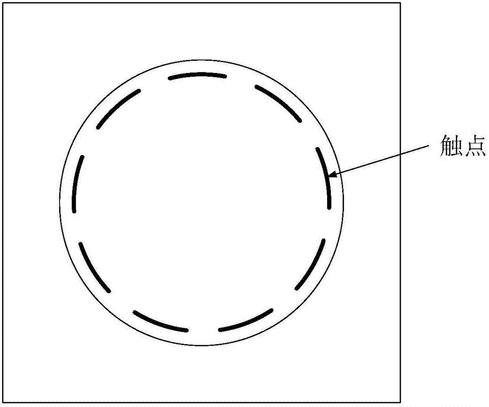
[0057] The induction sheet is set on one side of the knob.

[0058] The ring-shaped metal sheet is arranged on the induction sheet, and the projected areas of the ring-shaped metal sheet on the plurality of inductance detection devices are different.

[0059] Optionally, in the above embodiments of the present invention, the annular metal sheet is an annular copper sheet.

[0060] A plurality of inductance detection devices 35 are arranged inside the panel at posi...

Embodiment 3

[0088] According to an embodiment of the present invention, an embodiment of electrical equipment is provided, including: the knob wire controller according to any one of Embodiment 2.

[0089] According to the above embodiments of the present invention, the knob wire controller includes: a panel, a knob, a plurality of inductance detection devices and a processor, the knob is arranged on the panel through a pressing structure and rotated relative to the panel, and the plurality of inductance detection devices are arranged inside the panel , at a position corresponding to the projection of the knob, the processor is arranged inside the panel and connected to multiple inductance detection devices. During the operation of the knob, the processor acquires the parameter values ​​detected by multiple inductance detection devices, determines the operating state of the knob according to the parameter value, generates a control signal according to the parameter value and the operating ...


PUM


Abstract

The invention discloses a knob wire controller and a control method thereof as well as electrical equipment. The control method of the knob wire controller comprises the following steps of obtaining parameter values detected by a plurality of inductance detectors in a knob operation process; determining operation status of a knob according to the parameter values, wherein the operation status includes rotation operation status or press operation status; and generating a control signal according to the parameter values and the operation status, wherein the control signal is used for controlling parameters of the electrical equipment. According to the knob wire controller and the control method thereof as well as the electrical equipment, the technical problem of high cost of a light touch button wire controller or a touch screen wire controller in the existing technology is solved.

Description

technical field [0001] The invention relates to the field of electrical equipment control, in particular to a knob wire controller, a control method thereof, and electrical equipment. Background technique [0002] As electrical equipment becomes more and more intelligent, there are more and more functional requirements for electrical equipment, and correspondingly, the functional requirements for buttons are becoming more and more complex. At present, many home appliance buttons are operated by mechanical buttons, touch buttons, touch screens, etc. However, for mechanical buttons or touch buttons, there is a certain number of times of use, and the function is relatively single; for touch buttons or touch screens, the cost is high, and when there are water stains, oil stains, stains and other things on the hand, there will be improper operation. Sensitivity or no response after operation occurs. [0003] Aiming at the problem of high cost of the light-touch button wire contr...

Claims


Application Information

Patent Timeline
Patent Type & Authority Applications(China)
IPC IPC(8): H03K17/97
CPCH03K17/97H03K2017/9706
Inventor 刘泉洲姚果赖东锋唐杰贺小林叶铁英张亚国杨丽
Owner GREE ELECTRIC APPLIANCES INC
Why Eureka
Try Eureka