Heart rate module, electronic device for collecting heart rate and heart rate collecting method
A technology of heart rate and module, which is applied in the field of heart rate acquisition, heart rate module, and electronic devices for heart rate acquisition, which can solve problems such as low measurement accuracy, reflected waves susceptible to external interference, and poor user experience.
- Summary
- Abstract
- Description
- Claims
- Application Information
AI Technical Summary
Problems solved by technology
Method used
Image

Examples
Embodiment 1
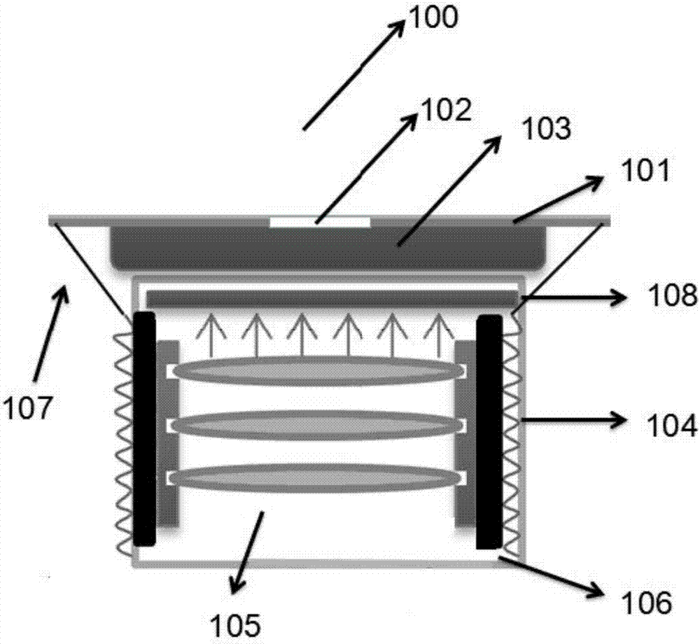
[0031] figure 1 It is a schematic structural diagram of a heart rate module according to an embodiment of the present invention, such as figure 1 As shown, a heart rate module includes a heart rate circuit board 101, a processor chip 102, a heart rate sensor 103, an electromagnetic coil 104, a lens assembly 105 and a guide rail 106; wherein, the heart rate sensor 103 is set at the heart rate On the circuit board 101, the guide rails 106 are arranged symmetrically on both sides of the front end of the heart rate sensor 103, the lens assembly 105 is arranged between the guide rails 106, the electromagnetic coil 104 is arranged around the guide rails 106, and the guide rails are magnetic substance, the processor chip 102 is electrically connected to the electromagnetic coil and the heart rate sensor respectively. It should be noted that the processor chip 102 is connected to the electromagnetic coil 104 through the conductive wire 107 . There are one or more lens assemblies 105...
Embodiment 2
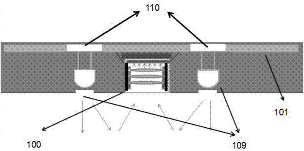
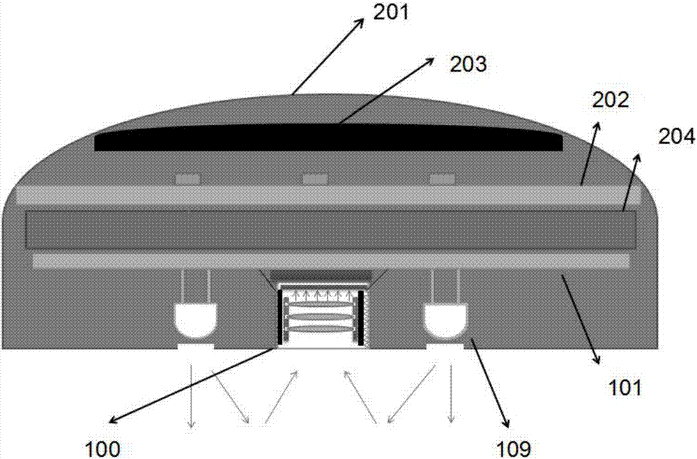
[0053] image 3 It is a schematic structural diagram of an electronic device for collecting heart rate according to an embodiment of the present invention, such as image 3 As shown, an electronic device for collecting heart rate, the electronic device includes a housing 201, a main control board 202 and the above-mentioned heart rate module 100; the heart rate module 100 is arranged on the lower surface of the housing 201, corresponding to The casing 201 at the position of the heart rate module 100 is provided with a light-transmitting hole, and the processor chip 102 of the heart rate module 100 is arranged on the main control board 202 . It should be noted that a light transmission hole is provided corresponding to the position of the lens assembly 105 and the position of the LED light 109 so that the heart rate module 100 can work normally. The processor chip 102 of the heart rate module 100 is arranged on the main control board 202, that is to say, in the electronic devi...
Embodiment 3
[0059] Figure 4 It is a flow chart of a heart rate acquisition method according to an embodiment of the present invention, such as Figure 4 as shown,
[0060] In step S310, guide rails are symmetrically arranged on both sides of the front end of the heart rate sensor, a lens assembly is arranged between the guide rails, and an electromagnetic coil is arranged around the guide rails;
[0061] In step S320, sending a voltage control signal that traverses the entire range to the electromagnetic coil, controlling the electromagnetic coil to generate different electromagnetic forces, so as to drive the guide rail to traverse the full range of motion of the electromagnetic coil;
[0062] In step S330, a plurality of heart rate measurement data collected by the heart rate sensor in real time during the guide rail traversing the full-scale movement of the electromagnetic coil;
[0063] In step S340, according to the plurality of heart rate measurement data, the optimal maintenance...
PUM
 Abstract
Description
Claims
Application Information
 - R&D
- Intellectual Property
- Life Sciences
- Materials
- Tech Scout
- Unparalleled Data Quality
- Higher Quality Content
- 60% Fewer Hallucinations
Browse by: Latest US Patents, China's latest patents, Technical Efficacy Thesaurus, Application Domain, Technology Topic, Popular Technical Reports.
© 2025 PatSnap. All rights reserved.Legal|Privacy policy|Modern Slavery Act Transparency Statement|Sitemap|About US| Contact US: help@patsnap.com