Screw rod transmission cutting machine

A technology of screw drive and cutting machine, which is applied in fur cutting, leather punching/punching/cutting, small raw hide/big raw hide/leather/fur mechanical treatment, etc. Inconsistent operation and receiving positions, unsatisfactory cutting efficiency, etc., to achieve the effect of small footprint, improved production efficiency, and convenient operation

Inactive Publication Date: 2017-08-25
DONGGUAN EMMA CNC TECH CO LTD
View PDF9 Cites 2 Cited by
  • Summary
  • Abstract
  • Description
  • Claims
  • Application Information

AI Technical Summary

Problems solved by technology

Due to structural constraints, the gear transmission type cutting machine has a large overall volume and occupies a large area. The independent operation table 5 and the receiving platform 6 have inconsistent

Method used


Image

  • Screw rod transmission cutting machine
  • Screw rod transmission cutting machine
  • Screw rod transmission cutting machine

Examples


Embodiment Construction

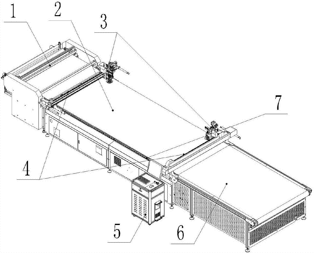
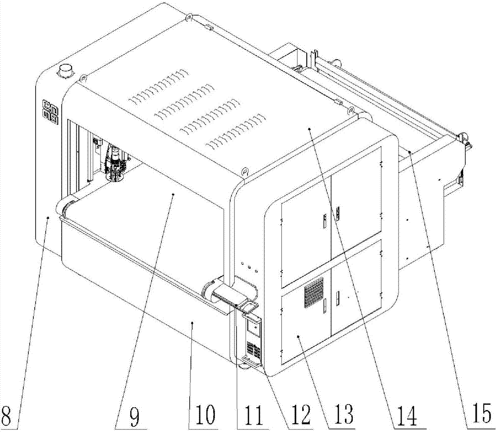
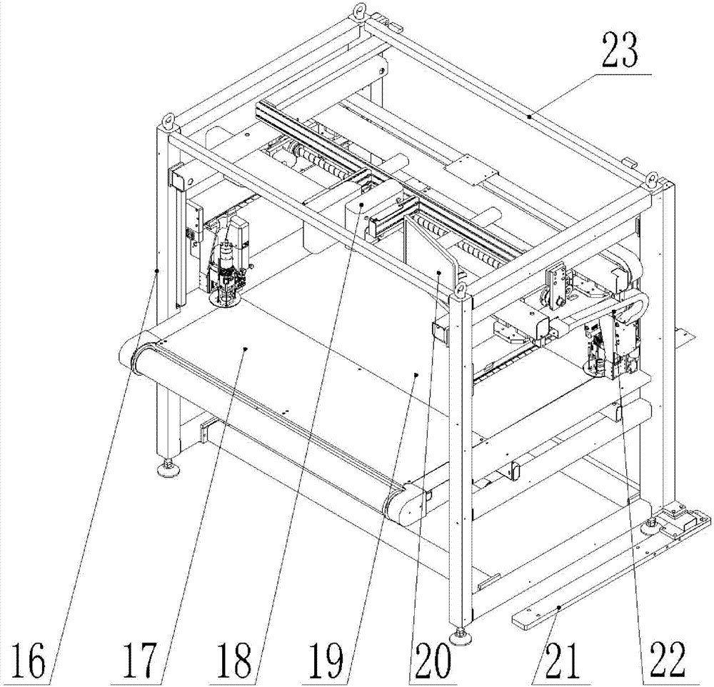
[0026] Such as figure 1 and figure 2 As shown, the screw drive cutting machine includes a frame, and the frame includes an underframe 16, and the underframe 16 is provided with an adsorption platform 19, and the front side of the adsorption platform 19 is provided with a receiving platform 17, and the adsorption The upper side of the platform 19 and the receiving table 17 is provided with a cutting mat 9 , and the front side of the receiving table 17 is provided with a receiving hopper 10 . The rear side of the adsorption platform 19 is provided with a feeder 15 for feeding the cutting platform. An upper bracket 23 is arranged above the underframe 16, and the upper bracket 23 is welded by square tubes. The outer side of the upper bracket 23 is provided with a casing 14, and the casing 14 is provided with ventilation holes. Four corners of the upper end of the housing 14 are provided with lifting lugs. The right side of the frame is provided with a projection stand 21 . A...


PUM


Abstract

The invention relates to a screw rod transmission cutting machine. The screw rod transmission cutting machine comprises a machine frame; the machine frame comprises a bottom frame and an upper bracket; the bottom frame is provided with an attraction platform and a material collecting platform, and the rear side of the attraction platform is provided with a feeder; a transverse transmission device comprises a transverse transmission screw rod fixed to the upper bracket, the outer sides of transverse transmission nuts are rotationally sleeved with transverse transmission nut installation plates, and nut driving devices are connected to the transverse transmission nuts; longitudinal transmission frames are connected to the transverse transmission nut installation plates, and a transverse transmission guiding device is arranged between the longitudinal transmission frames and the upper bracket; the longitudinal transmission frames are provided with longitudinal transmission screw rods rotationally and longitudinal driving motors; cutter bits are fixed to longitudinal transmission nuts, and longitudinal transmission guiding devices are arranged between the cutter bits and the longitudinal transmission frames; and an operation apparatus of a control device is adjacent to the material collecting platform. Power is transmitted through the screw rod nuts, and the transmission precision and cutting precision are high; and an operation platform is arranged at the position of the material collecting platform, operation and material collecting positions are the same, and operation is convenient.

Description

technical field [0001] The invention relates to a cutting device, in particular to a screw drive cutting machine. Background technique [0002] At present, science and technology are advancing by leaps and bounds, market competition is becoming increasingly fierce, and competition is ubiquitous in modern society. Product quality and output are fundamental to ensure that enterprises remain invincible in the fierce market competition. At present, in the production process of leather products, most automatic leather cutting machines use rack and pinion or synchronous wheel synchronous belt transmission. Such as figure 1 As shown, the gear transmission type cutting machine includes a working platform 2 and a feeding device 1 located on one side of the adsorption platform. A cutting device is arranged on the working platform 2. The cutting device is mainly driven by a rack and pinion. Two cutter heads 3 are installed on two sides respectively. On the longitudinal beam 4, the lo...

Claims


Application Information

Patent Timeline
IPC IPC(8): C14B5/00C14B15/10
CPCC14B5/00C14B15/10
Inventor 王炜棠陈永君
Owner DONGGUAN EMMA CNC TECH CO LTD
Why Eureka
Try Eureka