Microfluidic technology-based chemiluminescent immune tray and working method thereof

A technology of chemiluminescence immunity and microfluidic technology, which is applied in the field of microfluidics, can solve the problems of insufficient cleaning effect, achieve good cleaning effect, reduce costs, and speed up the reaction process

Active Publication Date: 2017-08-25
ZHEJIANG PUSHKANG BIOTECHNOLOGY CO LTD
View PDF5 Cites 8 Cited by
  • Summary
  • Abstract
  • Description
  • Claims
  • Application Information

AI Technical Summary

Problems solved by technology

This patent adopts the method of liquid replacement in the cleaning step, and the cleaning effect is relatively not thorough enough

Method used


Image

  • Microfluidic technology-based chemiluminescent immune tray and working method thereof

Examples


Embodiment 1

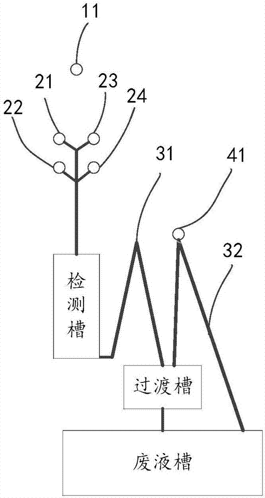
[0027] figure 1 A schematic diagram of the structure of the chemiluminescent immunodisc based on microfluidic technology in the embodiment of the present invention is given schematically, as shown in figure 1 As shown, the chemiluminescent immunodisc based on microfluidic technology includes:

[0028] Sample port 22, reagent port (including magnetic bead antibody inlet, enzyme-labeled antibody inlet and cleaning solution inlet) 21, 23-24 and detection tank; these are all existing technologies in the art, and will not be repeated here ;

[0029] transition groove; compared with the detection groove, the transition groove is farther away from the rotation center 11 of the disc; the minimum rotation radius of the transition groove is greater than the maximum rotation radius of the detection groove;

[0030] The first passage 31, one end of the first passage 31 communicates with the end of the detection groove away from the center of rotation, the other end communicates with the...

Embodiment 2

[0045] A chemiluminescent immune disk based on microfluidic technology in the embodiment of the present invention is different from embodiment 1 in that:

[0046] 1. The minimum rotation radius of the first channel is smaller than the minimum rotation radius of the detection groove.

[0047] 2. The inner wall of the first channel has a hydrophobic layer.

Embodiment 3

[0049] An application example of the chemiluminescent immunodisc and working method based on microfluidic technology in the chemiluminescent detection of alkaline phosphatase according to Example 2 of the present invention.

[0050] In this application example, the working method of the chemiluminescent immunodisc based on microfluidic technology, the working method includes the following steps:

[0051] Incubation phase:

[0052] The entire disk is placed in the detection chamber at 37°C, and the sample is added, with a volume between 1 and 50 microliters, typically 10 microliters;

[0053] Add magnetic bead antibody, the volume is between 1 and 100 microliters, typically 20 microliters;

[0054] Add the enzyme-labeled antibody, the volume is between 1 and 100 microliters, typically 20 microliters;

[0055] Start the motor, the typical speed of the disc rotation is 1500 rpm, and the liquid enters the reaction detection tank;

[0056] Entering the incubation stage, the moto...


PUM


Abstract

The invention provides a microfluidic technology-based chemiluminescent tray and a working method thereof. The microfluidic technology-based chemiluminescent immune tray comprises a sample adding port, a reagent port, and an assay cell; compared with the assay cell, a transition cell is farther away from the rotational center of the tray; one end of a first passage communicates with the end, which is far away from the rotational center, of the assay cell, the other end communicates with the transition cell, and the middle is a bent part; the minimum rotational radius of the first passage is less than the maximum rotational radius of the assay cell; compared with the transition cell, a waste liquid cell is farther away from the rotational center of the tray; and the transition cell communicates with the waste liquid cell. The invention has the advantages of little reagent consumption, short assay time, good cleaning effect and the like.

Description

technical field [0001] The invention relates to microfluidics, in particular to a chemiluminescent immune disc based on microfluidics technology and a working method thereof. Background technique [0002] At present, the popular automatic tube-type luminescent detection process is as follows: 1. Complete the mixed incubation of the sample, magnetic bead antibody, and enzyme-labeled antibody in the detection tube; 2. Use a magnet to absorb the magnetic beads on the tube wall and then suck the liquid away; 3. Remove the magnetic field, add the cleaning solution and mix the magnetic beads, use a magnet to absorb the magnetic beads on the tube wall and then suck the liquid away; 4. Repeat step 3 twice; 5. Remove the magnetic field, add the substrate and mix well Perform luminescence detection. [0003] Existing tubular chemiluminescence uses a relatively large amount of reagents. For chemiluminescence with high reagent costs, reducing the amount of reagents used can significant...

Claims


Application Information

Patent Timeline
Patent Type & Authority Applications(China)
IPC IPC(8): G01N35/00
CPCG01N35/00029G01N2035/00158G01N2035/00564
Inventor 陈坦程林金烨琦刘志远余波
Owner ZHEJIANG PUSHKANG BIOTECHNOLOGY CO LTD
Why Eureka
Try Eureka