Operation microscope support

An operating microscope and microscope technology, applied in the field of operating microscope brackets, can solve problems such as inconvenient operation of a balance arm, and achieve the effects of compact structure, convenient operation and simple operation.

Inactive Publication Date: 2017-08-25
苏州奥特科然医疗科技有限公司
View PDF3 Cites 3 Cited by
  • Summary
  • Abstract
  • Description
  • Claims
  • Application Information

AI Technical Summary

Problems solved by technology

[0004] Therefore, the technical problem to be solved by the present invention is to overcome the disadvantages of inconvenient operation of the balance arm in the prior art, thereby providing an operating microscope stand

Method used


Image

  • Operation microscope support
  • Operation microscope support
  • Operation microscope support

Examples


Embodiment 1

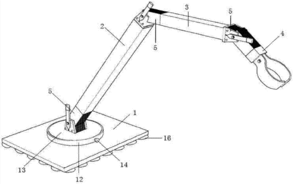
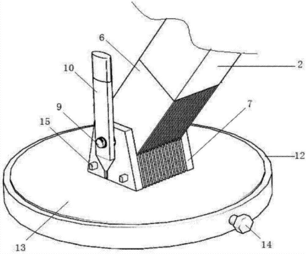
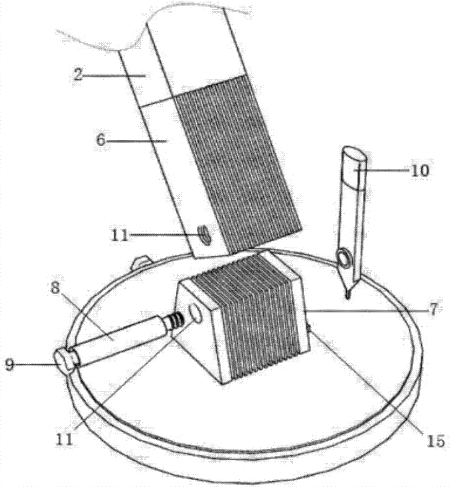
[0030] Figure 1-3 As shown, the operating microscope includes a microscope stand and a microscope body installed at the end of the microscope stand. The microscope stand includes a base 1, a support arm 2 installed on the base 1, a cantilever 3 installed on the support arm 2, and a cantilever The microscope fixture 4 at the end of 3; between the base 1 and the support arm 2, between the support arm 2 and the cantilever 3, and between the cantilever 3 and the microscope fixture 4 support are all connected by means of a fin positioning device 5; the fin positioning device 5 includes: A-fin group 6, B-fin group 7, shaft tube 8, fastening bolt 9, operating rod 10; A-fin group 6 and B-fin group 7 are formed by a plurality of fins arranged in parallel at equal intervals; The B fin group 7 is staggeredly embedded in the A fin group 6 and connected by the shaft tube 8; the two ends of the shaft tube 8 are respectively located in the shaft holes 11 on both sides of the A fin group 6; ...


PUM


Abstract

An operation microscope support comprises a pedestal, a support arm installed on the pedestal, a cantilever installed on the support arm and a microscope clamp installed on a cantilever tail end. The pedestal and the support arm, the support arm and the cantilever, and the cantilever and a microscope clamp support are connected through fin positioning devices. The cantilever is a telescoping cantilever mechanism. The telescoping cantilever mechanism comprises a transverse arm seat, a balance arm arranged on the transverse arm seat, a lens fixing seat and a balance arm engine base, wherein the lens fixing seat and the balance arm engine base are hinged to two ends of the balance arm respectively. Compared to the prior art, by using the support of the invention, locking is firm, operation is convenient, and the structure is compact and novel.

Description

technical field [0001] The invention relates to the technical field of microscopes, in particular to an operating microscope bracket. Background technique [0002] The balance arm is an important part of the connection between the main optical mirror and the base of the operating microscope. The displacement before and after the operation and the positioning during the operation are all controlled by the balance arm. After the lens is positioned during the operation, the balance arm needs to be locked at this position and cannot be moved. The existing balance arm is generally locked manually and mechanically. This method is very inconvenient to operate in aseptic surgery. [0003] At the same time, most existing adapters use shaft bolts to achieve rotation and positioning. This method can use the friction force generated by the tightening of the bolts as the braking force during positioning. When rotating, loosen the bolts properly to provide certain support. Force, reduce...

Claims


Application Information

Patent Timeline
Patent Type & Authority Applications(China)
IPC IPC(8): G02B21/00G02B21/24
CPCG02B21/0012G02B21/24
Inventor 朱文昱赵兵
Owner 苏州奥特科然医疗科技有限公司
Why Eureka
Try Eureka