Protective Structure and Protective Method for Protecting Core Instrument Line

A core instrumentation and protection structure technology, applied in the direction of reactors, greenhouse gas reduction, climate sustainability, etc., can solve the problems of long operation time, complicated hoisting tools and operation steps, large radiation dose, etc., and achieve easy replacement Effect

Active Publication Date: 2019-01-08
NUCLEAR POWER INSTITUTE OF CHINA
View PDF5 Cites 2 Cited by
  • Summary
  • Abstract
  • Description
  • Claims
  • Application Information

AI Technical Summary

Problems solved by technology

[0002] Nuclear reactors are generally equipped with dozens of core instruments used to measure the neutron flux rate of the core. During the operation of the reactor, these core instruments pass through the pressure vessel and the upper reactor internals, insert the fuel assembly, and stop the reactor. Before the pressure vessel is opened for refueling, it is necessary to extract these core instruments from the fuel assembly, and provide shielding and protection for a section of high-irradiation dose core instruments inserted into the fuel assembly. There are two commonly used solutions: one is Lift the core instruments one by one from the fuel assembly into the upper internals. This method is easy to get stuck in the upper internals due to the embrittlement of the core instruments after being irradiated. The radiation dose of personnel is relatively large, and the operation time is relatively long; the second is to set up a complex guide structure above the upper support column. In the instrument tube of the guide structure, this method needs to set up a complicated guide structure in the upper stack internals, which will affect the installation and maintenance of the control rod guide assembly, and the hoisting tools required by this method should be able to lift the guide structure and move it with the upper stack. The components are stored together, resulting in complicated lifting tools and operation steps

Method used


Image

  • Protective Structure and Protective Method for Protecting Core Instrument Line
  • Protective Structure and Protective Method for Protecting Core Instrument Line
  • Protective Structure and Protective Method for Protecting Core Instrument Line

Examples


Embodiment 1

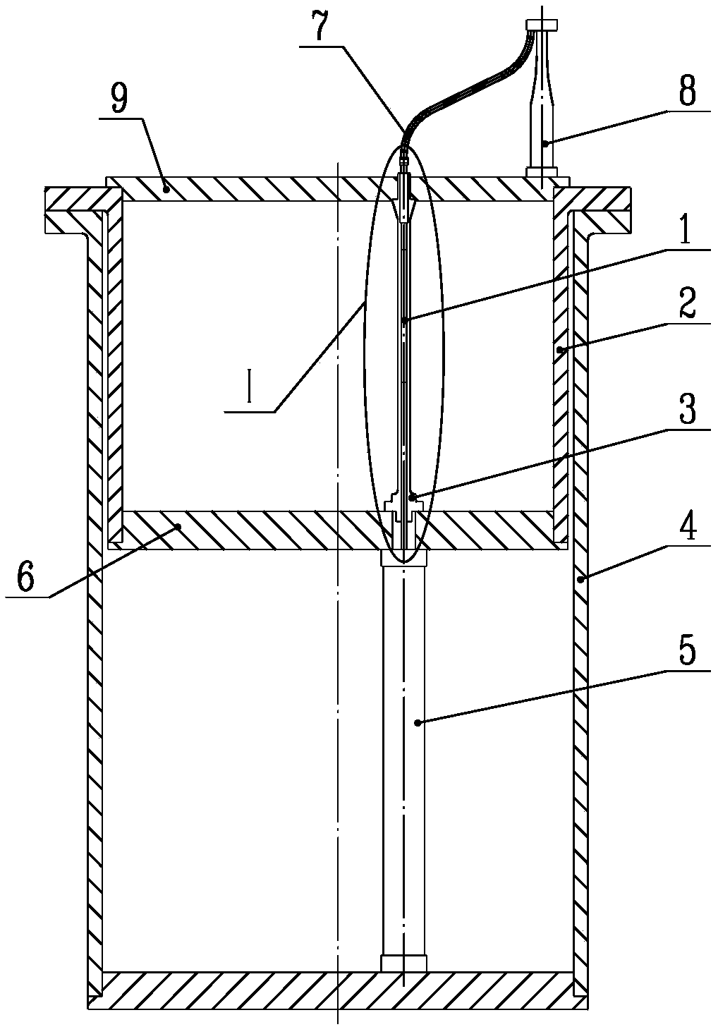
[0038] Such as Figure 1 to Figure 10 As shown, the protective structure for protecting the core instrumentation line includes the upper support column 3 belonging to the upper reactor internals 1, and also includes the casing for protecting the core instrumentation line 22. During the operation of the nuclear reactor, the casing is located on the upper support column 3 Inside, the core instrument line 22 is located in the casing; it is characterized in that, during nuclear reactor maintenance, the core instrument line 22 is stationary relative to the upper support column 3 and is integrally lifted with the upper reactor internals 1 and the upper support column 3, and the sleeve The pipe fittings can pass through the lower end of the upper support column 3 and move freely up to the bottom of the support column 3 and cover the end of the core instrumentation line 22 .

[0039] The design principle of the present invention is: in the prior art, there is a technology using the in...

Embodiment 2

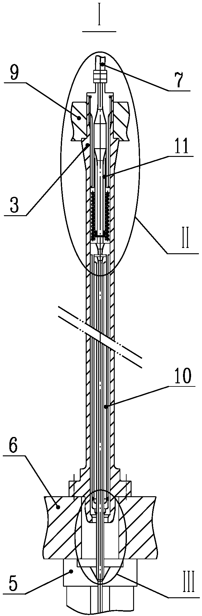
[0041] On the basis of the above-mentioned embodiments, for some types of reactors, since the length of the upper support column 3 is sufficient or the length inserted into the core instrument line 22 is relatively short, when the sleeve is a sleeve, the sleeve The pipe can pass through the lower end of the upper support column 3 and move freely up and below the upper support column 3, and the upper end of the sleeve is enlarged and can be captured by the constraint opening at the lower end of the upper support column 3. The structure of a bushing is not shown in the figure.

Embodiment 3

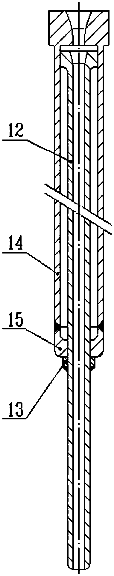
[0043] On the basis of the foregoing embodiments, for some types of reactors, when the length of the upper support column 3 is not enough or the length of the core instrumentation line 22 inserted into the core is relatively long, the casing member includes an outer casing 14 and is arranged in the outer casing 14. The inner sleeve 12; the outer sleeve 14 can pass through the lower end of the upper support column 3 and move freely below the upper support column 3, and the upper end of the outer sleeve 14 is enlarged and can be captured by the constraint port at the lower end of the upper support column 3; The inner sleeve 12 can pass through the lower end of the outer sleeve 14 to move freely below the support column 3 , and the upper end of the inner sleeve 12 is enlarged and can be captured by the constraint opening at the lower end of the upper support column 3 . This structure can use 2 casings to meet the requirement of the protection length, equivalently, the present inve...


PUM


Abstract

The invention discloses a protection structure for protecting the instrumentation line of the core and a protection method thereof. The protection structure for protecting the instrumentation line of the core includes an upper support column belonging to the upper internal components of the reactor, and also includes a sleeve for protecting the instrumentation line of the core. During the working period of the nuclear reactor, the casing part is located in the upper support column, and the core instrument line is located in the casing part; it is characterized in that, during the maintenance of the nuclear reactor, the core instrument line is stationary relative to the upper support column and integrated with the internal components of the reactor and the upper support column Lifting, the casing member can pass through the lower end of the upper support column and move freely under the upper support column and cover the end of the core instrumentation line.

Description

technical field [0001] The invention relates to a structural part for providing protection and shielding for core instruments, belonging to nuclear reactor internal components, in particular to a protection structure for protecting core instrument lines and a protection method thereof. Background technique [0002] Nuclear reactors are generally equipped with dozens of core instruments for measuring the neutron flux rate of the core. During the operation of the reactor, these core instruments pass through the pressure vessel and the upper reactor internals, insert the fuel assembly, and stop the reactor. Before the pressure vessel is opened for refueling, it is necessary to extract these core instruments from the fuel assembly, and provide shielding and protection for a section of high-irradiation dose core instruments inserted into the fuel assembly. There are two commonly used solutions: one is Lift the core instruments one by one from the fuel assembly into the upper inte...

Claims


Application Information

Patent Timeline
Patent Type & Authority Patents(China)
IPC IPC(8): G21C11/00
CPCG21C11/00Y02E30/30
Inventor 饶琦琦王留兵许斌张宏亮罗英陈训刚李娜刘晓颜达鹏肖聪宋锴
Owner NUCLEAR POWER INSTITUTE OF CHINA
Why Eureka
Try Eureka