Damping device for inhibiting windage yaw of transmission line insulators

A damping device and transmission line technology, applied in the field of damping devices, can solve the problems of friction damage at the connection of parts, increase the weight of the transmission line, increase the cost of the transmission line, etc., and achieve good insulation performance, simple structure, and avoidance of wind deflection flashover. Effect

Active Publication Date: 2017-08-25
NORTHEAST DIANLI UNIVERSITY
View PDF5 Cites 18 Cited by
  • Summary
  • Abstract
  • Description
  • Claims
  • Application Information

AI Technical Summary

Problems solved by technology

[0003] At present, the wind deflection devices commonly used in high-voltage transmission lines include weights, spacers, and windproof insulators. The problem of wind deflection of transmission line insulators, and the installation of many devices is relatively complicated, which may also bring other safety hazards
As far as the installation and operation process is concerned, the installation of most suppression devices is not simple. However, under the action of strong winds, the wind deflection of the transmission line produces a strong pulling force, and the heavy hammer, windproof pull wire and windproof string cannot fundamentally solve the problem. On the one hand, it is It is easy to be pulled and damaged, and on the other hand, it will bring extra weight or hidden dangers to the trans...

Method used


Image

  • Damping device for inhibiting windage yaw of transmission line insulators
  • Damping device for inhibiting windage yaw of transmission line insulators
  • Damping device for inhibiting windage yaw of transmission line insulators

Examples


Embodiment 1

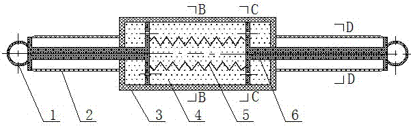
[0028] Embodiment 1, with reference to Figure 5 When in use, one end of the single damping device 11 is connected to the cross arm 8, and the other end is connected to the lower end of the insulator 10.

Embodiment 2

[0029] Embodiment 2, with reference to Image 6 , when in use, on the cross arm 8 located on both sides of the insulator 10, one end of the two damping devices 11 is connected to the cross arm 8, and the other end of the two damping devices 11 is connected to the lower end of the insulator 10 .

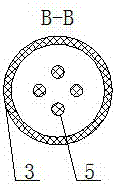
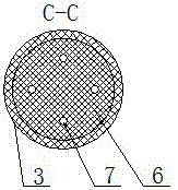
[0030] Under the action of strong wind load on the transmission line, the insulator 10 and the conductor will be wind deflected, and the conductor will produce a large horizontal displacement, which will reduce the structural distance between it and the tower 9, and the distance between the conductors will be reduced, resulting in conductor discharge and interphase flashover. When installed After the damping device 11, the spring 5 will firstly absorb a large amount of strong wind load, the piston rod of the piston 6 will produce relative displacement due to the force, and the piston 6 will absorb the energy of the wind load under the action of the damping medium 4, thereby ensuring t...


PUM


Abstract

The invention relates to a damping device for inhibiting the windage yaw of transmission line insulators, which is characterized by comprising a cylinder, a two-way piston, a spring, hinge seats, a protective sleeve, and an insulating damping medium. The two parts of the two-way piston arranged at an interval are disposed in the cylinder and in sliding fit with the cylinder. The two parts of the two-way pistons are connected by the spring arranged in the interval. The piston rod ends of the two-way piston are equipped with the hinge seats. The cylinder is filled with the insulating damping medium. The two-way piston is provided with damping holes for the insulating damping medium to circulate. The damping device is connected with an insulator and a cross arm through the hinge seats at the piston rod ends. The damping device has the advantages of simple structure, convenience of installation and maintenance, high strength, high elastic modulus, good shock absorption performance, resistance to high and low temperature, corrosion resistance, good insulation property, and long service life. When in use, the damping device is installed between the insulator and the cross arm of a transmission line. The damping device can absorb the vibration impact of strong wind to the insulator, avoid flashover of the transmission line caused by windage yaw, and ensures safe and stable operation of the transmission line.

Description

technical field [0001] The invention relates to the technical field of power transmission lines, and relates to a damping device for suppressing wind deflection of insulators of power transmission lines. Background technique [0002] As an important part of the power grid, overhead transmission lines play an important role in the power system. The safe operation of transmission lines is the key to ensuring the normal supply of electric energy. Due to the wide distribution of transmission lines and complex meteorological conditions, especially under the action of strong winds, it is very easy to cause wind deflection of transmission line insulators, resulting in phase-to-phase flashover of conductors and even tripping and power failure accidents. Under the influence of weather and terrain, it is generally not easy to judge and deal with the occurrence of wind deviation phenomenon, and due to the continuity of wind, wind deviation faults are generally not easy to reclose. The...

Claims


Application Information

Patent Timeline
IPC IPC(8): H02G7/12H02G7/14
CPCH02G7/125H02G7/14
Inventor 刘春城曲达郑忻王重阳
Owner NORTHEAST DIANLI UNIVERSITY
Why Eureka
Try Eureka