
Steel tube perforating device and working method thereof

A punching device and steel pipe technology, applied in the direction of feeding device, positioning device, storage device, etc., can solve the problems of not being suitable for mass production, increasing manual labor intensity, and high manual labor intensity, so as to reduce manual labor intensity, High degree of automation and the effect of improving production efficiency

Active Publication Date: 2017-08-29
漳钢(漳州)工贸有限公司
View PDF7 Cites 18 Cited by
  • Summary
  • Abstract
  • Description
  • Claims
  • Application Information

AI Technical Summary

Problems solved by technology

Using the electric drill drilling method, the position accuracy of the hole is poor, the labor intensity is high, the work efficiency is low, and it is not suitable for mass production; if the existing machine tool or stamping die is used, manual feeding and unloading are usually required when drilling. , and only one steel pipe can be punched at a time, which not only increases the labor intensity, but also reduces production efficiency

Method used


Image

  • Steel tube perforating device and working method thereof
  • Steel tube perforating device and working method thereof

Examples


Embodiment Construction

[0025] The present invention will be described in further detail below in conjunction with the accompanying drawings and specific embodiments.

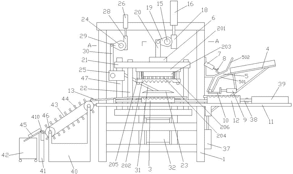
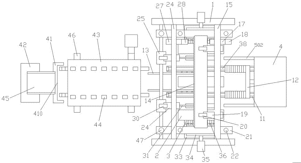
[0026] Such as Figure 1-2As shown, a steel pipe punching device of the present invention includes a frame 1, a steel pipe punching device and a steel pipe feeding device. The steel pipe punching device includes a punch seat 6 driven up and down by a first drive mechanism. The lower end of the mold base 6 is provided with several punches 2 at intervals along its length direction, and a die 3 is arranged directly below each of the punches 2, and the punch 2 and the die 3 cooperate to punch steel pipes; The dies 3 at the front and rear ends of the frame 1 are respectively provided with a positioning mechanism for axially positioning the steel pipes on the outer sides; The steel pipe conveying plate 4 of the hole steel pipe, the steel pipe conveying plate 4 is provided with a conveying slideway 5 near the end of the frame 1, and the upp...


PUM


Abstract

The invention relates to a steel tube perforating device and a working method thereof. The steel tube perforating device comprises a rack, a steel tube punching device and a steel tube feeding device; the steel tube punching device comprises a plurality of male dies, a female die is located under each male die, and positioning mechanisms used for conducting axial positioning on steel tubes are arranged outside the female dies at the front end and the rear end of the rack; the steel tube feeding device comprises a steel tube conveying plate arranged at one side of the rack in an inclined mode, a conveying slide channel is arranged at the end, close to the rack, of the steel tube conveying plate, a material blocking plate used for blocking a lower end outlet of the conveying slide channel is arranged at the lower side of the conveying slide channel, and lifting conveying racks extending into the rack are horizontally arranged at the lower side of the material blocking plate; and a conveying slide seat used for receiving the steel tubes is connected on the conveying racks in a sliding mode, the conveying slide seat conveys the steel tubes to the positions under the male dies and then moves downwards along with the conveying racks, so that the steel tubes fall on the female dies, and push rods used for pushing the steel tubes out of the female dies when the conveying racks rise are arranged at the end, located below the male dies, of the conveying racks. According to the steel tube perforating device, the design is reasonable, the automation degree is high, and not only is the production efficiency enhanced, but also the manual labor intensity is relieved.

Description

Technical field: [0001] The invention relates to a steel pipe punching device and a working method thereof. Background technique: [0002] When the steel pipe is in use, in order to facilitate the fixed connection with other parts, it is necessary to punch holes on the circumferential surface of the steel pipe. There are two main ways to drill holes in traditional steel pipes: (1) Manually fix the steel pipes, and then drill holes with electric drills; (2) Drill holes with machine tools or stamping dies. Using the electric drill drilling method, the position accuracy of the hole is poor, the labor intensity is high, the work efficiency is low, and it is not suitable for mass production; if the existing machine tool or stamping die is used, manual feeding and unloading are usually required when drilling. , and only one steel pipe can be punched at a time, which not only increases the labor intensity, but also has low production efficiency. Invention content: [0003] The ...

Claims


Application Information

Patent Timeline
IPC IPC(8): B21D28/28B21D43/16B21D43/13B21D43/00B21D43/20B21D45/02
CPCB21D28/28B21D43/003B21D43/006B21D43/13B21D43/16B21D43/20B21D45/003B21D45/02
Inventor 陈丽娟
Owner 漳钢(漳州)工贸有限公司
Features
  • Generate Ideas
  • Intellectual Property
  • Life Sciences
  • Materials
  • Tech Scout
  • Unparalleled Data Quality
  • Higher Quality Content
  • 60% Fewer Hallucinations
Learn More