Spray assembly and spray device

A technology of nozzle assembly and seal, applied in the direction of spray device, spray device, etc., can solve the problems of increasing difficulty in spraying range control, slow spray start and stop speed, etc., to avoid slow spray start and stop speed, The effect of reducing the difficulty of control

Active Publication Date: 2017-08-29
SZ DJI TECH CO LTD
View PDF6 Cites 2 Cited by
  • Summary
  • Abstract
  • Description
  • Claims
  • Application Information

AI Technical Summary

Problems solved by technology

Due to the trapped gas in the internal flow channel of the existing nozzle device, the speed o

Method used


Image

  • Spray assembly and spray device
  • Spray assembly and spray device
  • Spray assembly and spray device

Examples


Embodiment Construction

[0066] The following will clearly and completely describe the technical solutions in the embodiments of the present invention with reference to the accompanying drawings in the embodiments of the present invention. Obviously, the described embodiments are only some, not all, embodiments of the present invention. Based on the embodiments of the present invention, all other embodiments obtained by persons of ordinary skill in the art without making creative efforts belong to the protection scope of the present invention.

[0067] It should be noted that when a component is said to be "fixed" to another component, it can be directly on the other component or there can also be an intervening component. When a component is said to be "connected" to another component, it may be directly connected to the other component or there may be intervening components at the same time. When a component is said to be "set on" another component, it may be set directly on the other component or t...


PUM


Abstract

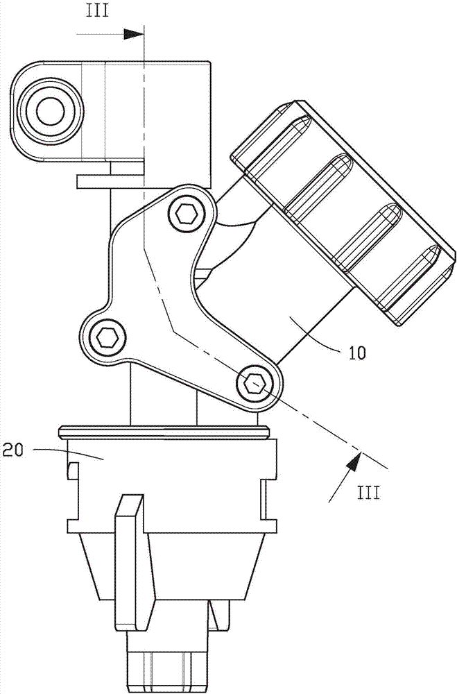
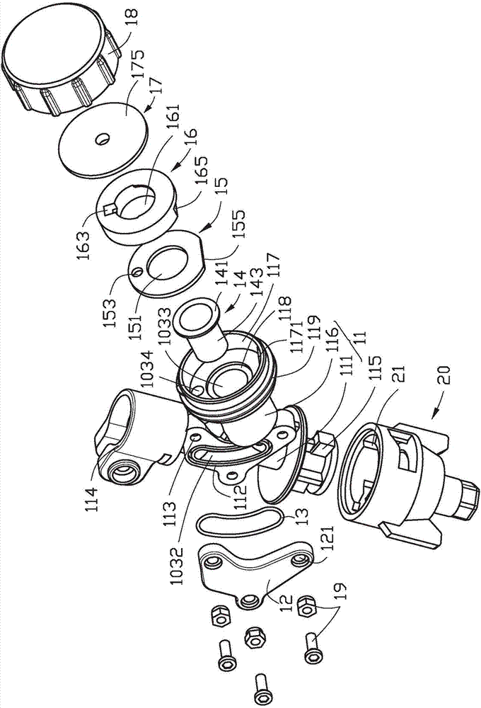
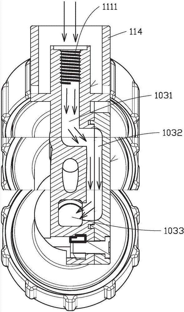
A spray assembly includes a pipeline structure 101 comprising a liquid inlet 102, a flow way 103 and a valve port 104 disposed in the flow way 103 and connected with the flow way 103; a valve core mounted in the flow way 103 and used for controlling the opening and closing of the valve port 104, wherein the flow way 103 includes a gas outlet flow way 1033 arranged in a manner of being tilt relative to the central axis of the liquid inlet 102. The valve port 104 is arranged at the top end of the gas outlet flow way 1033 and the bottom end of the gas outlet flow way 1033 is connected with the liquid inelt 102.

Description

technical field [0001] The invention relates to a spray head assembly and a spray head device with the spray head assembly. Background technique [0002] The spraying system is used for spraying pesticides, fertilizers, water and other liquids in agricultural production, plant protection and other fields. The sprinkler unit installed at the end of the sprinkler system pipeline is used to spray liquid onto the crop surface. Due to the stagnant gas in the internal flow channel of the existing sprinkler device, the speed of starting and stopping the spraying is relatively slow, which makes it more difficult to control the spraying range. Contents of the invention [0003] In view of this, it is necessary to provide a spray head assembly that solves the above problems and a spray head device including the spray head assembly. [0004] A spray head assembly, comprising: [0005] The pipeline structure includes a liquid inlet, a flow channel and a valve port, the valve port i...

Claims


Application Information

Patent Timeline
IPC IPC(8): B05B1/30B05B15/06
CPCB05B1/3006B05B1/30B05B15/40B05B1/36
Inventor 金峙良吴旭民吴晓龙卢绰莹周乐
Owner SZ DJI TECH CO LTD
Why Eureka
Try Eureka