Spray pipe structure for underwater welding and underwater welding equipment

An underwater welding and nozzle technology, applied in welding equipment, arc welding equipment, metal processing equipment, etc., can solve problems such as turbidity, achieve the effects of reducing smoke, reducing high-temperature gasification, and improving welding accuracy

Pending Publication Date: 2022-03-11
梁柯
View PDF9 Cites 0 Cited by
  • Summary
  • Abstract
  • Description
  • Claims
  • Application Information

AI Technical Summary

Problems solved by technology

[0006] Aiming at the deficiencies in the prior art, the present invention provides a nozzle structure for underwater welding, which solves the problem of water vapor generated during the welding process, hydrogen and oxygen generated by water ionization in the prior art , Bubbles, turbid smoke and other oxides produced by the burning of the electrode coating, and a series of problems brought about

Method used


Image

  • Spray pipe structure for underwater welding and underwater welding equipment
  • Spray pipe structure for underwater welding and underwater welding equipment
  • Spray pipe structure for underwater welding and underwater welding equipment

Examples


Embodiment Construction

[0034] The technical solutions in the present invention will be further described below in conjunction with the accompanying drawings and embodiments.

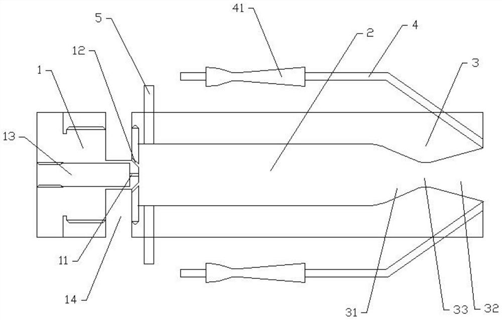
[0035] like figure 1 As shown, the embodiment of the present invention proposes a nozzle structure device for underwater welding, including a nozzle, which includes an injector 1, a combustion chamber 2 and a nozzle 3 connected in sequence, wherein the injector 1 A number of injection ports are respectively provided on the upper part of the injection port. One end of the inlet of the injection port is connected with a fuel passage. There is a sealed connection between them, so that one end of the outlet of the injection port communicates with the combustion chamber 2. It should be noted that the end face connecting the injector 1 and the combustion chamber 2 is a plane, and the outlet of the injection port is located on this end face. The nozzle 3 includes a converging section 31 and a diverging section 32 arranged sequential...


PUM


Abstract

The spray pipe structure comprises a fuel tank and a spray head, the spray head comprises an injector, a combustion chamber and a spray pipe which are sequentially connected, the injector is provided with a plurality of injection openings, the spray pipe comprises a convergence section and an expansion section which are sequentially arranged from inside to outside, and the spray pipe structure further comprises a gas supply assembly matched with the spray head. The gas supply assembly comprises a high-pressure gas cylinder, a valve and a first gas supply pipe, the valve is arranged at an outlet of the high-pressure gas cylinder and connected with the first gas supply pipe, and the first gas supply pipe is arranged at the tail end of the expansion section of the spray pipe and matched with the orientation of the spray pipe. High-pressure gas is sprayed out at the outlet of the spraying pipe through the gas supply assembly, so that a small-range water-free area is manufactured, liquid fuel is sufficiently combusted in advance through the combustion chamber, then the range of sprayed flame is adjusted through the convergent section and the expansion section of the spraying pipe, the flame is controlled in the water-free area, and therefore the flame can be fully combusted under the condition that the flame does not make direct contact with water. And welding work is carried out.

Description

technical field [0001] The invention relates to the technical field of underwater welding equipment, in particular to a nozzle structure for underwater welding and underwater welding equipment. Background technique [0002] Due to the existence of water, underwater welding makes the welding process more complicated, and there will be various problems that are not encountered in land welding. At present, the underwater welding process can be roughly divided into three types: wet underwater welding, dry underwater welding and partial dry underwater welding. Among them, the wet underwater welding technology is an underwater welding method in which the welder directly welds underwater instead of artificially draining the water around the welding area. Wet underwater welding is widely used and can be applied to most underwater welding environments. [0003] In wet underwater welding, the arc burns underwater, similar to submerged arc welding, in that it burns in bubbles. When ...

Claims


Application Information

Patent Timeline
Patent Type & Authority Applications(China)
IPC IPC(8): B23K9/00
CPCB23K9/0061B23K9/00
Inventor 梁柯周庆宇李东禧彭德康
Owner 梁柯
Why Eureka
Try Eureka