
Ceramic milling cutter

A technology of cutters and milling devices, applied in the direction of milling cutters, cutters for milling machines, milling machine equipment, etc.

Inactive Publication Date: 2017-08-29
SANDVIK INTPROP AB
View PDF8 Cites 1 Cited by
  • Summary
  • Abstract
  • Description
  • Claims
  • Application Information

AI Technical Summary

Problems solved by technology

Cubic boron nitride is harder than ceramics, but has the disadvantage of being more expensive than ceramics

Method used


Image

  • Ceramic milling cutter
  • Ceramic milling cutter
  • Ceramic milling cutter

Examples


Embodiment Construction

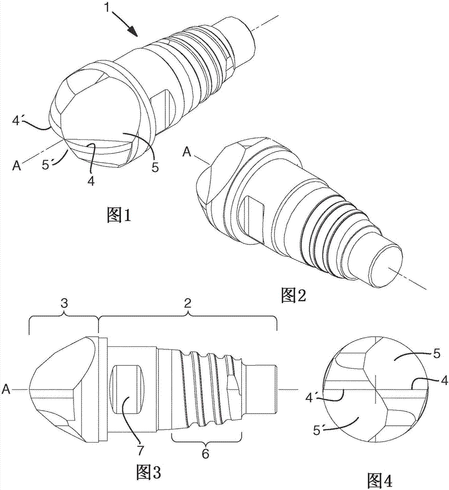
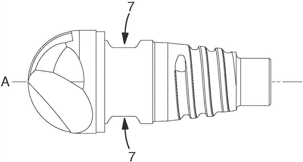
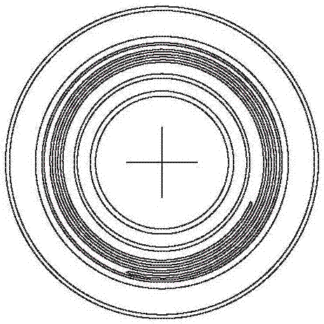
[0033] Figure 1-6 A milling device ( 1 ) according to a first embodiment is shown, which shows a milling device ( 1 ) of the exchangeable head type. The milling device (1) is rotatable in one direction about a longitudinal central axis (A) defining a forward direction or direction and an opposite rearward direction or direction. The milling device (1) comprises a front part (3) and a rear part (2) joined or brazed to each other by joints. Such as image 3 As shown, the front part (3) extends only in the forward direction or forward direction relative to the joint and the rear part (2) only extends in the opposite direction relative to the joint, said opposite direction being the rearward direction or backward direction. Further in the rearward direction or upward than the rear (2) is a rotating machine tool spindle (not shown), which is part of a machine tool such as a machining center or other CNC machine (not shown). The milling device (1) can be connected to a rotating ...


PUM


Abstract

The invention relates to a milling device (1), rotatable in one direction around a longitudinal center axis (A) defining a forward direction and an opposite rearward direction, comprising a front part (3) and a rear part (2). The front part (3) comprising cutting edges (4, 4') each having a longitudinal extension, the front part (3) comprising chip flutes (5, 5') each having a longitudinal extension, the front part (3) is made of a monolithic piece of ceramic. The rear part (2) is configured to be fixed in a rotatable tool body or a rotatable chuck. The rear part (2) is made of a monolithic piece of cemented carbide. A front end surface of the rear part (2) having a smaller area than a rear end surface of the front part (3), the front end surface of the rear part (2) and a rear end surface of the front part (3) being permanently bonded or brazed to each other by a joint.

Description

technical field [0001] The present invention generally relates to a milling device. More precisely, the invention relates to a milling device according to the preamble of claim 1 . The invention also relates to a milling tool comprising such a milling device and to a method of producing such a milling device. Background technique [0002] For metal cutting tools, many cutting tool materials, ie the materials of the cutting edges of the cutting tools, are known. Cutting tool materials are distributed in separate and distinct material groups such as high-speed steel, carbide, ceramics, cubic boron nitride and diamond. These materials have different chemical compositions and have different characteristics and properties, especially in relation to toughness and hardness, especially at high temperatures at or near the cutting edge during cutting. [0003] One of the goals of past and present cutting tool material development is to develop materials with high toughness and high...

Claims


Application Information

Patent Timeline
Patent Type & Authority Applications(China)
IPC IPC(8): B23C5/10
CPCB23C5/10B23C2210/02B23C2210/03B23C2226/18B23C2240/08B23C2222/28C04B37/026C04B2237/125C04B2237/126C04B2237/127C04B2237/343C04B2237/368C04B2237/401C04B2237/76C04B2237/86B23C5/006B23C5/18B23C2240/32
Inventor 埃曼努埃尔·戴维卡米耶·桑达吉安
Owner SANDVIK INTPROP AB
Features
  • Generate Ideas
  • Intellectual Property
  • Life Sciences
  • Materials
  • Tech Scout
  • Unparalleled Data Quality
  • Higher Quality Content
  • 60% Fewer Hallucinations
Learn More