Single shaft eccentric screw pump
An eccentric screw pump, single-shaft technology, applied in the direction of pumps, pump components, pump control, etc., can solve the problems of pushing, discharging pressure, discharging fluid, and unable to flow fully, so as to prevent the stator from wear and tear Effect
- Summary
- Abstract
- Description
- Claims
- Application Information
AI Technical Summary
Problems solved by technology
Method used
Image


Examples
no. 1 approach
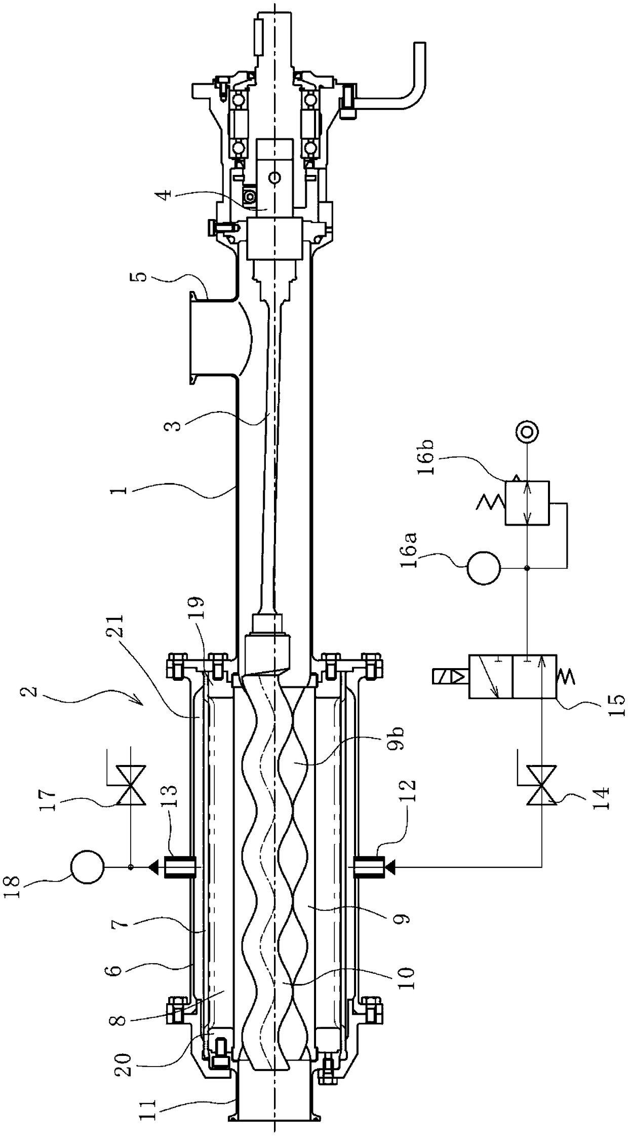
[0038] figure 1 The uniaxial eccentric screw pump according to the first embodiment is shown. The uniaxial eccentric screw pump has a driver (not shown) provided at one end of a housing 1 and a pump body 2 provided at the other end.
[0039] The casing 1 is formed of a metal material in a cylindrical shape, and accommodates the coupling rod 3 . One end of the coupling rod 3 is connected to the coupling 4 so as to transmit the power from the driving machine. In addition, a connection pipe 5 is connected to the outer peripheral surface on one end side of the case 1 so that a fluid can be supplied from a tank or the like not shown.
[0040] The pump main body 2 accommodates a sleeve 7 , an outer casing 8 , a stator 9 , and a rotor 10 in a stator case 6 , and end studs 11 are attached to ends of the stator 9 .
[0041] The case 1 is connected to one end portion of the stator case 6 by connecting the flange portions to each other with bolts and nuts. In addition, the flange po...
no. 2 approach
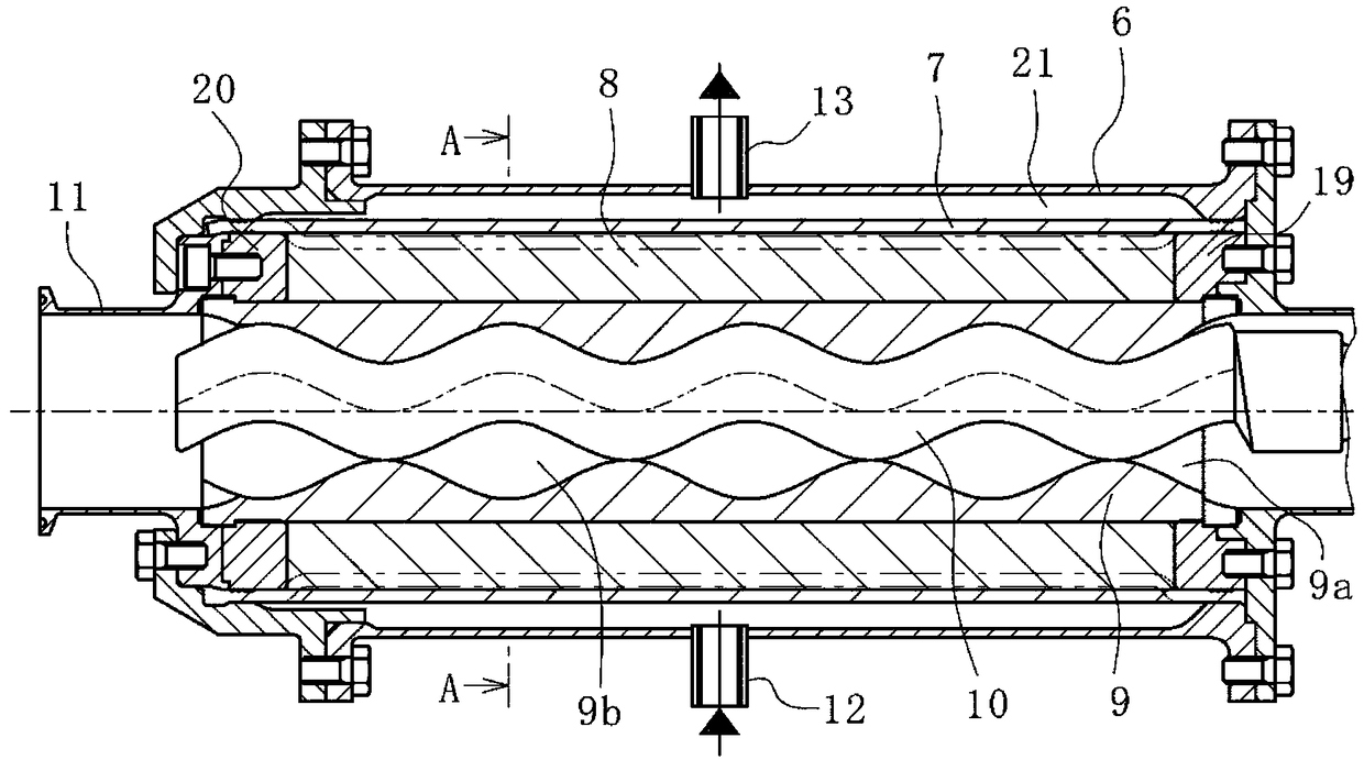
[0062] Figure 4 The uniaxial eccentric screw pump according to the second embodiment is shown. This uniaxial eccentric screw pump is different from the first embodiment described above in the following points. In addition, in the following description, the same code|symbol is attached|subjected to the same part as 1st Embodiment, and the description is abbreviate|omitted.
[0063] The outer periphery of the stator 9 is provided with the outer casing 8 (the first outer casing part 28 and the second outer casing part 29 ) and the wound body 25 wound to position them around the stator 9 . The winding body 25 is an example of the holding member of the present invention. Then, the control fluid is injected into the sealed space 21 formed by the stator case 6 and the sleeve 7 arranged on the inner diameter side, and the sleeve 7 is expanded to the inner diameter side. The stator 9 is pressurized radially inwardly with the second case portion 29 .
[0064] An injection port 26 i...
PUM
 Abstract
Description
Claims
Application Information
 - R&D
- Intellectual Property
- Life Sciences
- Materials
- Tech Scout
- Unparalleled Data Quality
- Higher Quality Content
- 60% Fewer Hallucinations
Browse by: Latest US Patents, China's latest patents, Technical Efficacy Thesaurus, Application Domain, Technology Topic, Popular Technical Reports.
© 2025 PatSnap. All rights reserved.Legal|Privacy policy|Modern Slavery Act Transparency Statement|Sitemap|About US| Contact US: help@patsnap.com