Multi-cylinder hermetic compressor

A hermetically sealed compressor technology, which is applied in mechanical equipment, machines/engines, liquid fuel engines, etc., can solve problems such as inability to effectively set flow paths, and achieve the effects of preventing increase, preventing pressure loss, and improving compressor efficiency

Active Publication Date: 2019-04-23
MITSUBISHI ELECTRIC CORP
View PDF8 Cites 0 Cited by
  • Summary
  • Abstract
  • Description
  • Claims
  • Application Information

AI Technical Summary

Problems solved by technology

[0008] However, no matter in any of the above-mentioned method (1) or the above-mentioned method (2), it is necessary to arrange a refrigerant flow path in the limited space of the compression part.
Therefore, the enlargement of the flow path area is limited, and there is a problem that the flow path cannot be efficiently set.

Method used


Image

  • Multi-cylinder hermetic compressor
  • Multi-cylinder hermetic compressor
  • Multi-cylinder hermetic compressor

Examples


Embodiment approach 1

[0033] Embodiments of the present invention will be described below.

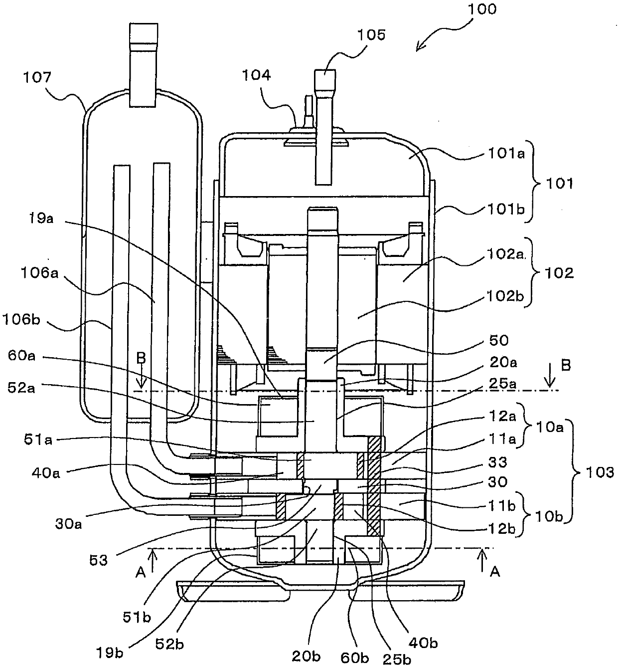
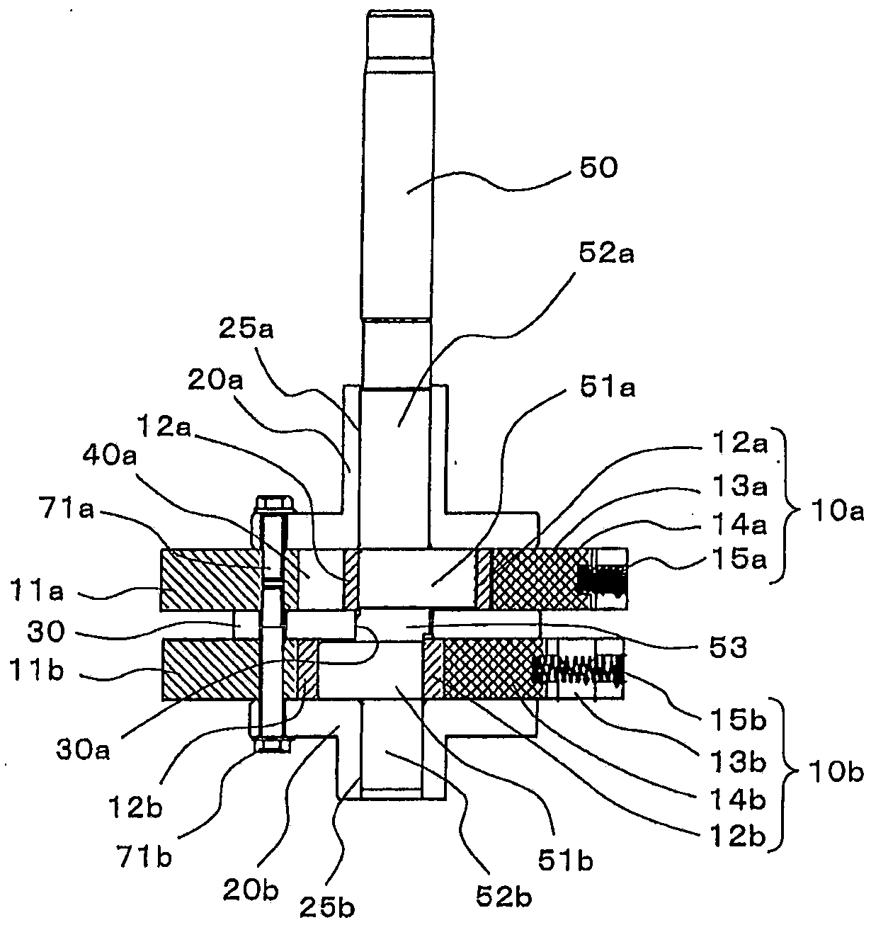
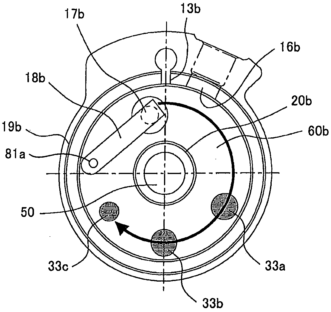
[0034] figure 1 It is a cross-sectional side view showing the overall structure of the multi-cylinder hermetic compressor according to Embodiment 1 of the present invention. figure 2 yes means figure 1 Partial cross-sectional view of the side view of the compression section of the multi-cylinder hermetic compressor. image 3 yes figure 1 A-A arrow direction sectional view. Figure 4 yes figure 1 Sectional view in the direction of the B-B arrow. In addition, since each figure above is drawn schematically, this invention is not limited to embodiment shown in figure.

[0035] Such as Figure 1 ~ Figure 4 As shown, the multi-cylinder hermetic compressor 100 according to Embodiment 1 includes a casing 101 as a hermetic container, a motor unit (hereinafter referred to as "motor") 102 as a driving source provided inside the casing 101, and a 101 inside the compression part 103 . Hereinafter, the configur...

Embodiment approach 2

[0080] Figure 7 is equivalent to showing the shape of the inlet and outlet of the refrigerant passage in the multi-cylinder hermetic compressor according to Embodiment 2 of the present invention. image 3 cutaway view. Figure 8 yes Figure 7 The cross-sectional view in the direction of arrow D-D shows the structure of the second end plate 20b. In addition, in the drawings, the same reference numerals as in the above-mentioned first embodiment are attached to the same functional parts as those in the above-mentioned first embodiment. In addition, in the description, refer to the above figure 1 as well as figure 2 .

[0081] In the multi-cylinder hermetic compressor 100 according to Embodiment 2, as Figure 7 as well as Figure 8 As shown, openings (which may be tapered or chamfered) 33d, 33e, 33f are provided at the inlets and outlets of the refrigerant passages 33a, 33b, 33c, and the openings 33d, 33e, 33f The cross-sectional area of ​​the cross-sectional area of ​​...


PUM


Abstract

A multi-cylinder hermetic compressor which comprises a first muffler chamber, a second muffler chamber, and a plurality of coolant channels which connect the first muffler chamber and the second muffler chamber. A check valve having a reed valve structure and comprising a fixed end at one end is provided at the first muffler chamber side in a first discharge port. The first discharge port is disposed so as to be shifted, relative to the fixed end, in one direction of rotation in the circumferential direction centred on a crank shaft. A coolant channel, from among the plurality of coolant channels, that is disposed in the position furthest from the first discharge port in the abovementioned direction of rotation has a smaller cross-sectional area than at least one of the other coolant channels.

Description

technical field [0001] The invention relates to a multi-cylinder hermetic compressor with multiple compression mechanisms. Background technique [0002] A hermetic compressor includes a hermetic container (hereinafter referred to as "casing"), a motor unit (hereinafter referred to as "motor") arranged in the housing, and a compression unit driven by the motor. [0003] In such a hermetic compressor, the refrigerant supplied through the suction pipe is compressed in the compression section, discharged into the casing through the muffler chamber, and discharged outside the casing through the discharge pipe. This hermetic compressor is used, for example, in refrigerators, freezers, air conditioners, water heaters, and the like, and thus high efficiency and low cost are required. [0004] In addition, in the case of a single-cylinder hermetic compressor having a single cylinder, the compression unit is constituted by a single compression mechanism. The compression mechanism in...

Claims


Application Information

Patent Timeline
Patent Type & Authority Patents(China)
IPC IPC(8): F04C18/356
CPCF04C18/356
Inventor 深谷笃义杉浦干一朗
Owner MITSUBISHI ELECTRIC CORP
Why Eureka
Try Eureka