Method for laser microdissection, and laser microdissection system

A technology of laser microdissection and laser beam, which is applied in microscopes, laser welding equipment, preparation of test samples, etc., and can solve problems such as multi-time

Active Publication Date: 2017-08-29
LEICA MICROSYSTEMS CMS GMBH
View PDF9 Cites 3 Cited by
  • Summary
  • Abstract
  • Description
  • Claims
  • Application Information

AI Technical Summary

Problems solved by technology

The same disadvantage applies to automatic methods, since the image-specific evaluation necessary for this takes considerable time even in modern evaluation systems

Method used


Image

  • Method for laser microdissection, and laser microdissection system
  • Method for laser microdissection, and laser microdissection system

Examples


Embodiment Construction

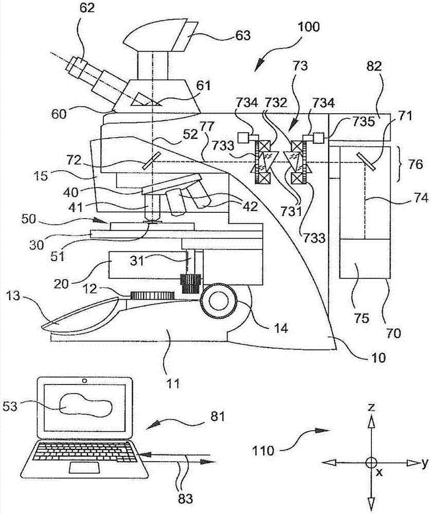
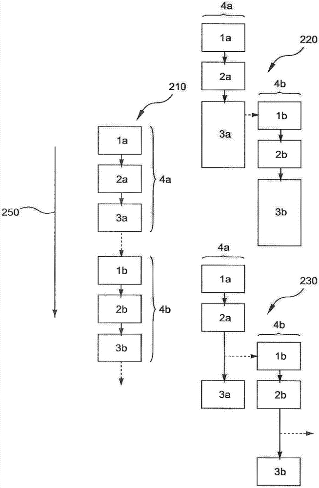
[0057] refer to figure 1 with figure 2 , shows an embodiment of a method (220, 230) for laser microdissection and a laser microdissection system for very fast ablation of cuts. In a laser microdissection system (100), at least a portion of an object (51) to be cut is detected in an image-generating manner (1a) and a first digital object image (53) is concomitantly generated; based on the first digital object image (53 ) defines (2a) a first processing instruction; then, by means of the laser beam (74) of the laser microdissection system (100), the object (51) is processed (3a) in a first processing step according to the first processing instruction. According to an embodiment of the invention, at least part of an object (51) is detected in image-generating manner (1b) and a second digital object image (53) is concomitantly generated; during the execution of the first processing step, based on the second digital object image ( 53) Define (2b) a second processing specificatio...


PUM


Abstract

A method for laser microdissection includes detecting at least a portion of an object to be dissected in an image-producing manner in a laser microdissection system and generating a first digital object image. A first processing specification is defined based on the first digital object image. In a first processing step, the object is processed using a laser beam of the laser microdissection system in accordance with the first processing specification. At least a portion of the object is detected in an image-producing manner and a second digital object image is generated. A second processing specification is defined during execution of the first processing step based on the second digital object image. In a second processing step, the object is processed using the laser beam of the laser microdissection system in accordance with the second processing specification.

Description

technical field [0001] The present invention relates to a method of laser microdissection and to a laser microdissection system for carrying out the method. Background technique [0002] Methods of processing biological specimens by laser microdissection have existed since the mid-1970s and have been continuously improved since then. [0003] In laser microdissection, cells, tissue regions, etc. can be isolated by a laser beam from the object to be dissected and can be recovered as a so-called "dissectate". A particular advantage of laser microdissection is that the brief contact between the object and the laser beam causes very little modification of the object. Specific recovery of cuttings can be accomplished in a number of ways. [0004] In known methods, the cuttings can be isolated from the object, for example by means of an infrared or ultraviolet laser beam; the cuttings fall in response to gravity into a suitable cuttings collection container. The cutout can also...

Claims


Application Information

Patent Timeline
Patent Type & Authority Applications(China)
IPC IPC(8): G01N1/28B23K26/38
CPCB23K26/38G01N1/286G01N2001/2886G02B21/32G02B21/06G02B21/365G06V20/69
Inventor 福尔克·施劳德拉夫安德鲁·李弗洛里安·霍夫曼
Owner LEICA MICROSYSTEMS CMS GMBH
Why Eureka
Try Eureka