Bi-camera scanner gun and scanning method thereof
A dual-camera and scanning method technology, applied in the field of barcode scanning, can solve problems such as limited application range, and achieve the effects of improving the sensitivity of use, expanding the range of use distance, and shortening the scanning time.
- Summary
- Abstract
- Description
- Claims
- Application Information
AI Technical Summary
Problems solved by technology
Method used
Image

Examples
Embodiment 1
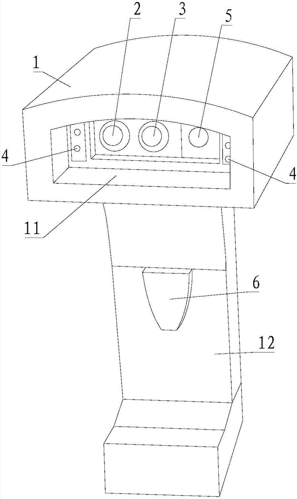
[0055] Please refer to figure 1 , Embodiment 1 of the present invention is:
[0056] A dual-camera scanning gun, including a housing 1, also includes a near-focus camera 2 and a far-focus camera 3, the housing 1 is provided with a scanning window 11, and the near-focus camera 2 and the far-focus camera 3 are installed on the At the scanning window 11, the near-focus camera 2 and the far-focus camera 3 are horizontally arranged side by side. It is convenient to align the near-focus camera 2 and the far-focus camera 3 at the barcode to be scanned at the same time.
Embodiment 2
[0057] Please refer to figure 1 , the second embodiment of the present invention is:
[0058] A dual-camera scanning gun, on the basis of Embodiment 1, further includes a supplementary light 4, a laser positioning light 5, a light grid, a buzzer, and a scanning button 6, and the supplementary light 4 is installed on the housing 1 at the scanning window 11; preferably, the supplementary light 4 is symmetrically installed at the left and right edges of the scanning window 11 of the housing 1; the laser positioning lamp 5 is installed at the scanning window 11 of the housing 1 place; the laser positioning light 5 is installed between the near-focus camera 2 and the far-focus camera 3, or the laser positioning light 5 is installed on the outer side of the near-focus camera 2 or the outer side of the far-focus camera 3, The laser positioning lamp 5 is a high-brightness infrared focusing LED lamp, and the light grid is installed in front of the laser positioning lamp 5; the buzzer ...
Embodiment 3
[0096] Please refer to figure 2 , Embodiment three of the present invention is:
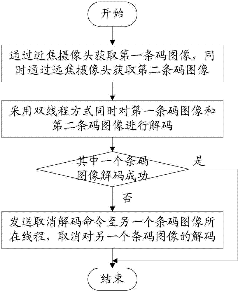
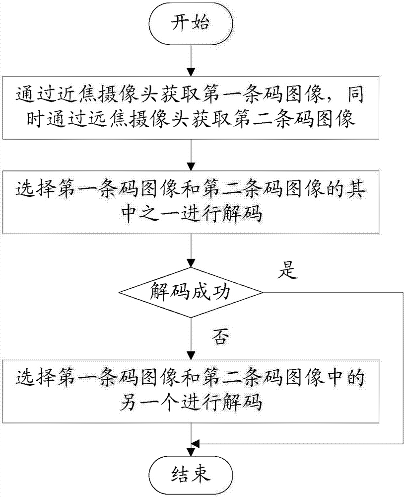
[0097] A dual-camera scanning gun scanning method, the method is:
[0098] Obtain the first barcode image through the near-focus camera, and obtain the second barcode image through the far-focus camera at the same time;
[0099] Decode the first barcode image and the second barcode image, specifically:
[0100] Simultaneously decode the first barcode image and the second barcode image in a dual-thread manner;
[0101] After one barcode image in the first barcode image and the second barcode image is successfully decoded, a cancel decoding command is sent to the thread where the other barcode image is located to cancel the decoding of the other barcode image.
PUM
 Abstract
Description
Claims
Application Information
 - R&D
- Intellectual Property
- Life Sciences
- Materials
- Tech Scout
- Unparalleled Data Quality
- Higher Quality Content
- 60% Fewer Hallucinations
Browse by: Latest US Patents, China's latest patents, Technical Efficacy Thesaurus, Application Domain, Technology Topic, Popular Technical Reports.
© 2025 PatSnap. All rights reserved.Legal|Privacy policy|Modern Slavery Act Transparency Statement|Sitemap|About US| Contact US: help@patsnap.com