Cone forming mold

A technology for forming molds and cones, used in forming tools, manufacturing tools, household appliances, etc., can solve the problems of difficult to guarantee the surface quality of cones, high skill requirements for processors, low processing efficiency, etc. The effect of good degree and high pass rate

Active Publication Date: 2019-02-15
CHINA HANGFA SOUTH IND CO LTD
View PDF5 Cites 0 Cited by
  • Summary
  • Abstract
  • Description
  • Claims
  • Application Information

AI Technical Summary

Problems solved by technology

[0004] The invention provides a cone molding die to solve the technical problems of long processing period, high labor intensity, low processing efficiency, difficulty in guaranteeing the surface quality of the cone after molding and high skill requirements for processors in the manual knocking molding method.

Method used


Image

  • Cone forming mold
  • Cone forming mold
  • Cone forming mold

Examples


Embodiment Construction

[0027] The embodiments of the present invention will be described in detail below with reference to the accompanying drawings, but the present invention can be implemented in many different ways defined and covered by the claims.

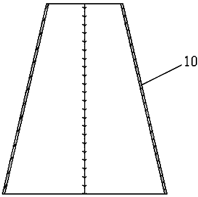
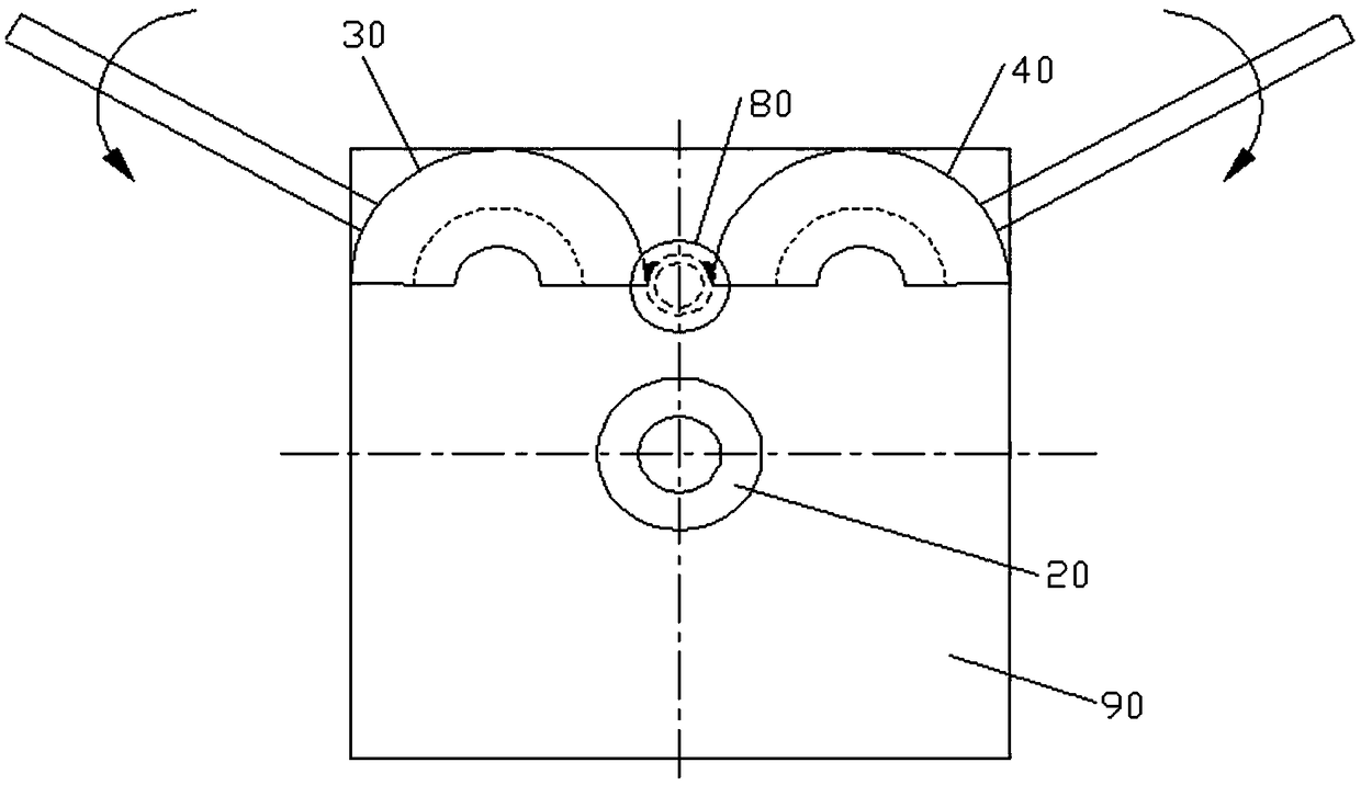
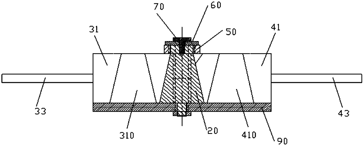
[0028] refer to figure 1 , figure 2 , Figure 4 and Figure 6 , the preferred embodiment of the present invention provides a cone forming die, which is used to circularly form the fan-shaped plate-shaped material roll into a cone 10. The cone forming die includes: a vertically arranged inner mold column 20, for Close the first forming outer mold 30 and the second forming outer mold 40 to clamp the inner mold column 20, the first forming outer mold 30 and the second forming outer mold 40 are opened and closed around the vertical fixed axis, and the first forming outer mold When the mold 30 and the second forming outer mold 40 close together to clamp the inner mold column 20, the outer ring surface of the inner mold column 20 and the first forming...


PUM


Abstract

The invention discloses a taper tube molding die. The taper tube molding die comprises a vertically-arranged inner die column, a first molding outer die and a second molding outer die, the first molding outer die and the second molding outer die are folded to be used for clamping the inner die column, and the first molding outer die and the second molding outer die are arranged around a vertical fixed shaft in an opening and closing manner; and when the first molding outer die and the second molding outer die are folded to be used for clamping the inner die column, a molding ring cavity used for molding a taper tube is formed amount the outer ring face of the inner die column and the first molding outer die and the second molding outer die. A molding pressing block is further installed on the inner die column to be used for abutting against a top arc line of a fan-shaped material in the process that the fan-shaped material is molded into the taper tube so as to limit axial displacement of the fan-shaped material along the inner die column, and the fan-shaped material is prevented from moving out of the molding ring cavity. According to the taper tube molding die, the part machining time can be greatly shortened, the part molding efficiency is improved, the quality of molded parts is stable, the surface quality is obviously improved, the part roundness is good, the one-time submitting and checking yield is high, the part molding process is simple in operation, and the requirement for the technical ability of an operator is low.

Description

technical field [0001] The invention relates to the field of cone forming, in particular to a cone forming die. Background technique [0002] The flame tube is a key component of the engine for fuel-air mixing and combustion. The materials of the rings at the head of the flame tube are GH1140 and GH3044 respectively, and the thickness of the material is t1.5. After rolling, the diameters at both ends of the cone 10 are required to be φ105, φ49, and the height is 90, as shown in the attached picture figure 1 shown. [0003] At present, the existing round rolling machines on the market have relatively large specifications, and are used for rolling round and conical tubes 10 with a diameter of φ320-6000mm. Since the diameter of the cone tube 10 at the head of the flame tube is small, it is not suitable for the existing round rolling machines on the market. machine. In the prior art, the cone 10 of the flame tube head is formed by manual beating, that is, a fitter uses a simp...

Claims


Application Information

Patent Timeline
Patent Type & Authority Patents(China)
IPC IPC(8): B21D37/10B21D5/00B21D51/10
CPCB21D5/00B21D37/10B21D51/10
Inventor 何飞迎方敬敬
Owner CHINA HANGFA SOUTH IND CO LTD
Why Eureka
Try Eureka