Magnetic Fastener Clips

A firmware clip and magnetic technology, applied in the direction of fixtures, vehicle components, superstructure sub-assemblies, etc., can solve problems such as difficulty in replacing installed and disconnected clips, improve reliability and quality, reduce manufacturing time, Reduce the effect of attachment

Active Publication Date: 2020-06-16
TERMAX CORP
View PDF5 Cites 0 Cited by
  • Summary
  • Abstract
  • Description
  • Claims
  • Application Information

AI Technical Summary

Problems solved by technology

Additionally, it can be difficult to replace an installed, disconnected clip

Method used


Image

  • Magnetic Fastener Clips
  • Magnetic Fastener Clips
  • Magnetic Fastener Clips

Examples


Embodiment Construction

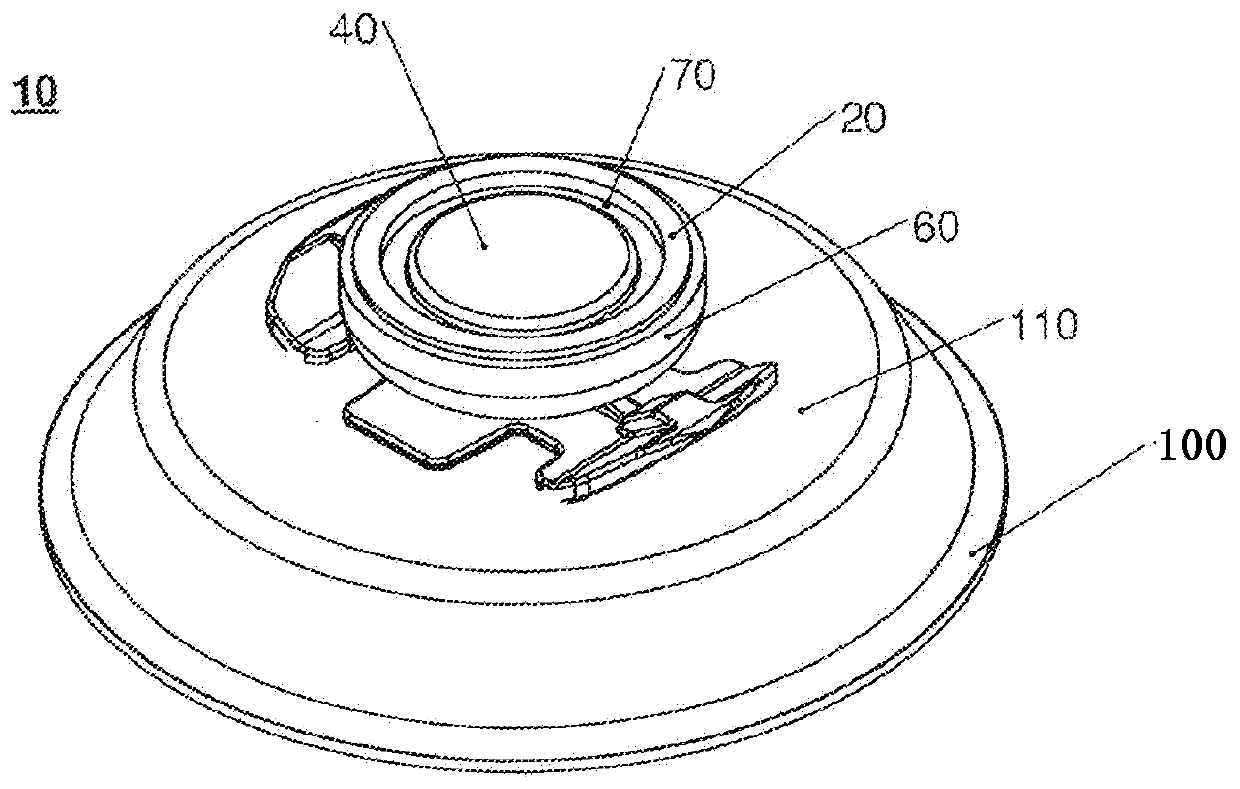
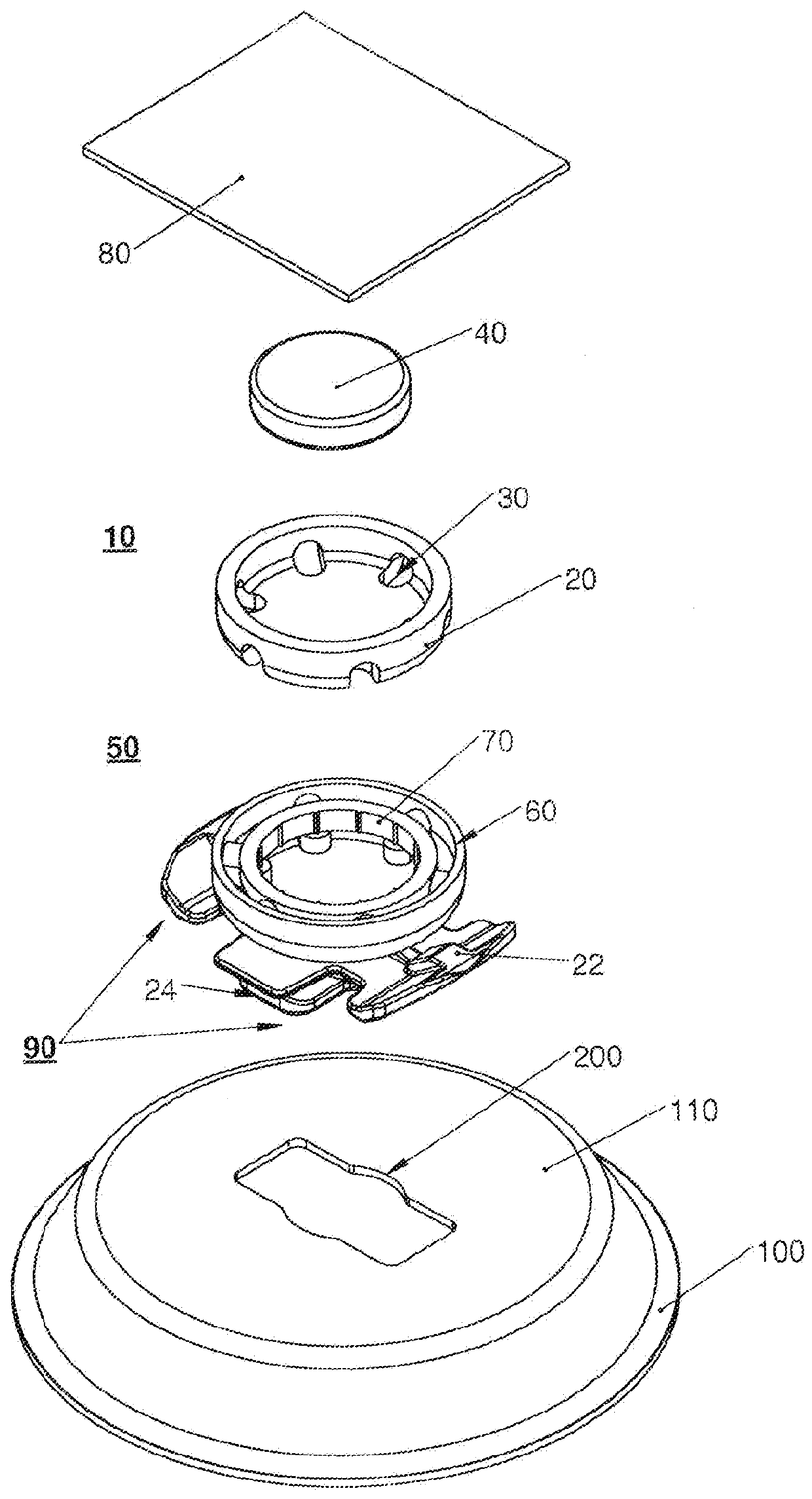
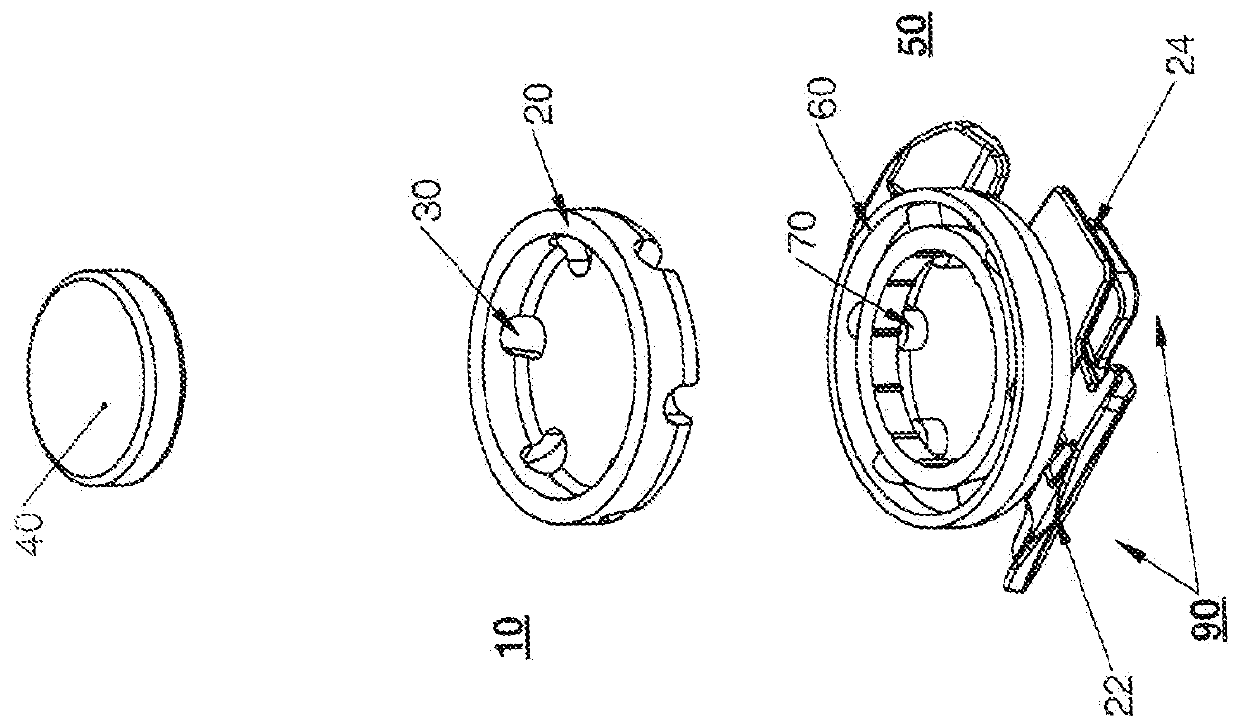
[0034] figure 1 , figure 2 with image 3 is a perspective view of a magnetic fastener clip 10 according to an embodiment. The magnetic fastener clip 10 includes: a cup 20 having at least one hole 30 ; a magnet 40 ; and an overmold 50 attached to the cup 20 . The overmold 50 has: a cup lid 60 attached to the outer side of the cup 20; and an inner ring 70 attached to the inner side of the cup 20; and optionally Coupling 90. The inner ring 70 may be attached to the cup lid 60 via the at least one hole 30 . The magnets 40 are operably attached into the inner ring 70, for example via glue, press fit or any suitable attachment. According to one embodiment, the cup lid 60 and the inner ring 70 are injection molded on at least a portion of the cup 20 to form the inner ring 70 and the cup lid 60 . The magnetic fastener clip 10 is operable for blind attachment into a structure 80 such as a vehicle chassis, ie a door frame, chassis or roof.

[0035] Such as Figure 3-7 An option...


PUM


Abstract

The present invention provides a magnetic fastener clip comprising a cup having at least one hole, an overmold attached to the cup and a magnet. The overmold has the cup lid injection molded on the outer side of the cup and the inner ring injection molded on at least a portion of the inner side of the cup. The inner ring is attached to the cup lid via the at least one hole. Magnets are operably attached to the inner ring. According to one embodiment, the swivel coupling is attached to the cup lid. The magnetic fastener clip is operable for blind attachment into structures such as vehicle chassis, ie pillars, door frames, chassis or roof.

Description

[0001] related application [0002] This application claims priority to U.S. Application 15 / 335,415 and to U.S. Provisional Application 62 / 299,597, Docket No. P055H, entitled "Magnetic Fastener Clip," filed February 25, 2016 priority. This application 62 / 299,597 is claiming priority to an application entitled "Magnetic Fastener Clip," docket number P055F and serial number 14 / 622,893, filed February 15, 2015 Continuation-in-Part of Application 14 / 622,893 claiming application titled "Magnetic Fastener Clip," Docket No. P055D, Serial No. 13 / 831,525, filed March 14, 2013 Continuation-in-Part of Priority Application 13 / 831,525 Claiming Application No. 12 / 983,010 entitled "Magnetic Fastener Clip," Docket No. P55A and filed December 31, 2010 Continuation-in-Part of Priority to U.S. Patent 8,287,034, dated October 16, 2012, which claims the title "Magnetic Fastener Clip," Docket No. P055 12 / 464,867 and a continuation-in-part of priority to U.S. Patent 8,615,852 filed May 13, 2009 and...

Claims


Application Information

Patent Timeline
Patent Type & Authority Patents(China)
IPC IPC(8): B60R13/02B62D27/06
CPCB62D27/06B60R13/0206B60R13/0256B60R13/025B60R13/0243B60R13/0212F16B2200/83
Inventor 迈克尔·蒂雷尔丹尼尔·詹姆斯·迪金森约翰·克拉森
Owner TERMAX CORP
Why Eureka
Try Eureka