Optimization-based measurement matrix imaging method

An imaging method and measurement matrix technology, applied in image enhancement, image analysis, image data processing, etc., can solve problems such as poor image effects, artifacts, and unsatisfactory image effects, and achieve faster convergence and optimal solutions precise effect

Inactive Publication Date: 2017-09-01
NORTHEASTERN UNIV
View PDF7 Cites 6 Cited by
  • Summary
  • Abstract
  • Description
  • Claims
  • Application Information

AI Technical Summary

Problems solved by technology

[0004] However, the images restored by the MRI system using Cartesian sampling matrix are not good enough and contain artifacts
In addition, using a single spiral sampling matrix or a two-dimensional variable density random sampling matrix can restore the image effect in the magnetic resonance imaging system is not ideal, the edge information of the image cannot be better collected and the integrity of the information cannot be guaranteed.

Method used


Image

  • Optimization-based measurement matrix imaging method
  • Optimization-based measurement matrix imaging method
  • Optimization-based measurement matrix imaging method

Examples


Embodiment 1

[0053] Such as figure 1 As shown, the present embodiment provides an imaging method based on an optimized measurement matrix, the method comprising:

[0054] Step 01: Perform Fourier transform on the target image to obtain K-space data.

[0055] Step 02: Use the sampling matrix to sample the K-space data to obtain the sampling signal for transmission.

[0056] In this embodiment, the variable-density radial annulus-like sampling matrix may be obtained by superimposing the radial sampling matrix and the annulus-like sampling matrix, and is suitable for a sampling matrix that satisfies an incoherence property with a sparse matrix.

[0057] That is to say, the variable-density radial ring-like sampling matrix is ​​generated according to the pre-defined radial sampling matrix and the sampling density function of the radial sampling matrix, the ring-like sampling matrix and the sampling density function of the ring-like sampling matrix.

[0058] Step 03: Sparse transform the targ...

Embodiment 2

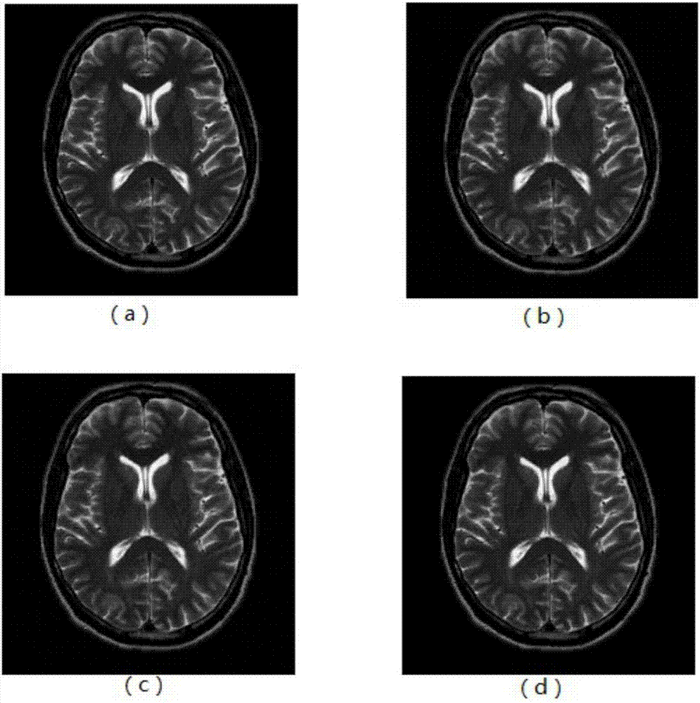
[0104] In this embodiment, the method for image reconstruction can be realized based on the optimization of the measurement matrix of CS-MRI, and the specific implementation steps are as follows:

[0105] Step 1: Select an appropriate sparse transformation base (ie sparse matrix) to perform sparse transformation on the target image.

[0106] For example, a wavelet transform may be chosen. Discrete cosine transform and singular value sparse transform as sparse matrix.

[0107] The second step: use variable density radial ring-like sampling matrix as sampling methods under various sparse transformation bases.

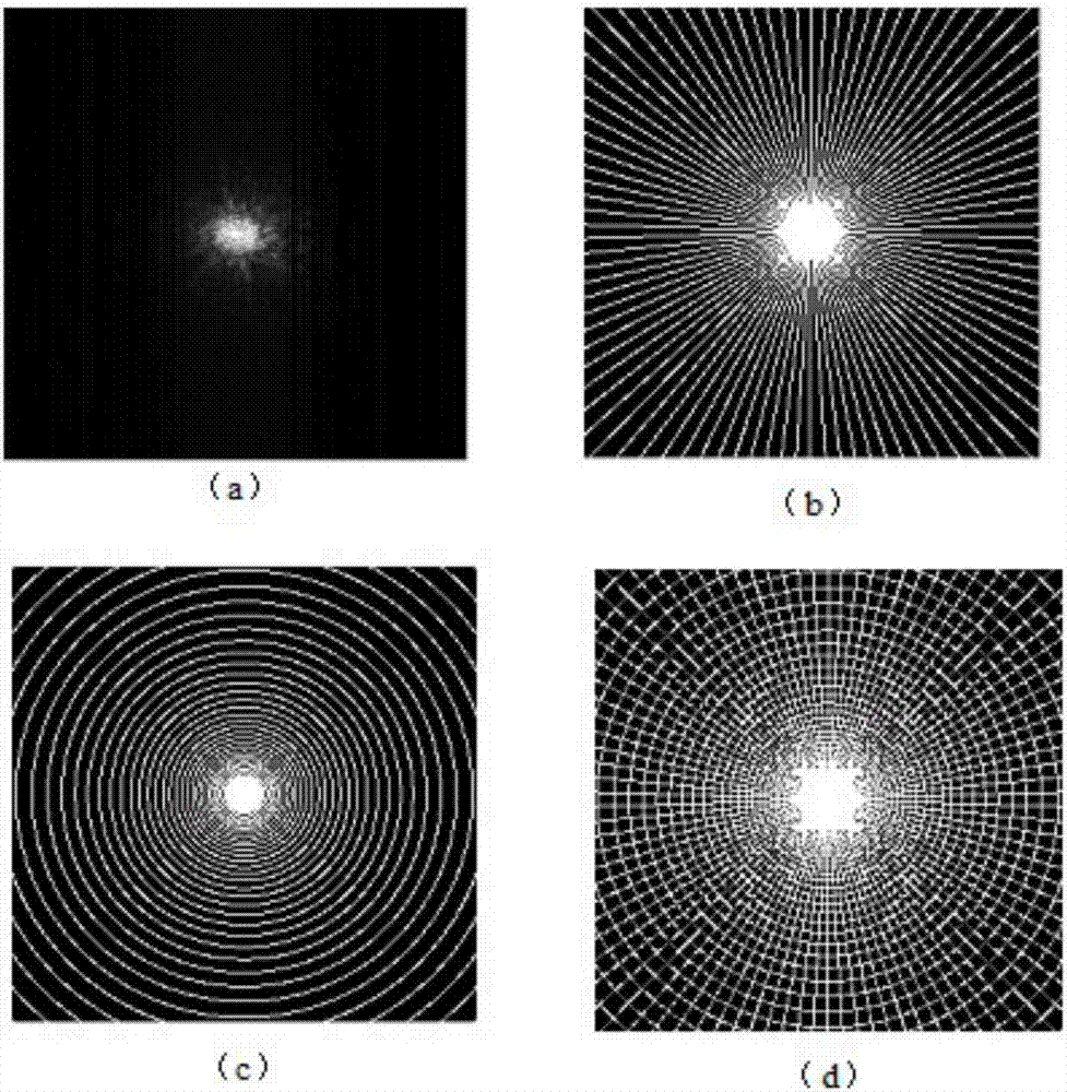
[0108] In order to express more intuitively and clearly the information of the improved sampling matrix Φ (that is, the variable-density radial ring-like sampling matrix). The following sampling rate is 30%, and the improved sampling matrix is ​​expressed, such as figure 2 shown.

[0109] From figure 2 It can be seen that the improved sampling matrix collects a hig...


PUM


Abstract

The invention provides an optimization-based measurement matrix imaging method. The method comprises the steps: 01) carrying out Fourier transform on a target image to obtain K-space data; 02) carrying out sampling on the K-space data through a sampling matrix to obtain sampled signals for transmission; 03) carrying out sparse transformation on the target image to enable a reconstructed signal to be K-sparse; 04) obtaining sparse coefficients through the sampled signals; and 05) carrying out processing on the sparse coefficients through a fast iteration threshold algorithm to obtain a reconstructed image, wherein the sampling matrix is obtained by carrying out superposition on a random radial sampling matrix and a similar circular ring sampling matrix, and is a variable-density radial similar circular ring matrix meeting non-coherence characteristics with the sparse matrix. The variable-density radial similar circular ring matrix in the method has high randomness and easily meets the non-coherence characteristics with the sparse matrix, so that an image recovery effect is good.

Description

technical field [0001] The invention relates to magnetic resonance imaging technology, in particular to an imaging method based on an optimized measurement matrix. Background technique [0002] In compressed sensing theory, the design of measurement matrix plays a very important role in the process of signal acquisition and reconstruction. Whether the selection of the measurement matrix is ​​reasonable directly affects the sparsity of the compressed sensing sampling signal, thus affecting the number of observations of the original signal by the reconstruction algorithm and the quality of the reconstructed image. [0003] In the compressed sensing-magnetic resonance imaging (CS-MRI) model, the measurement matrix is ​​also called the sampling matrix, which is the k-space sampling matrix in the magnetic resonance imaging system. The sampling matrix can greatly affect the performance of compressed sensing and reconstructed images. the quality of. Commonly used sampling matrice...

Claims


Application Information

Patent Timeline
Patent Type & Authority Applications(China)
IPC IPC(8): G06T5/00G06T5/10
CPCG06T5/001G06T5/10G06T2207/10088G06T2207/20052G06T2207/20056
Inventor 郎俊冮凯旋张江娜
Owner NORTHEASTERN UNIV
Why Eureka
Try Eureka