
A thermal control device for a stack assembly

A combination and thermal control technology, which is applied in the field of satellite temperature control, can solve the problems of large heat consumption, distribution, centralized stacking and assembly heat dissipation, and achieve the effect of improving heat dissipation

Active Publication Date: 2019-01-25
AEROSPACE DONGFANGHONG SATELLITE
View PDF7 Cites 0 Cited by
  • Summary
  • Abstract
  • Description
  • Claims
  • Application Information

AI Technical Summary

Problems solved by technology

[0003] The purpose of the present invention is to overcome the above-mentioned deficiencies in the prior art, and provide a thermal control device for a stacked assembly, which solves the problem of large heat consumption, distributed centralized stacked assembly, and heat dissipation

Method used


Image

  • A thermal control device for a stack assembly
  • A thermal control device for a stack assembly
  • A thermal control device for a stack assembly

Examples


Embodiment Construction

[0023] Below in conjunction with accompanying drawing and specific embodiment the present invention is described in further detail:

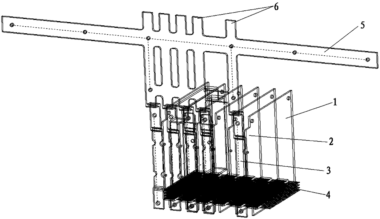
[0024] The present invention combines the electrical interface and mechanical interface of the stack assembly, adds circuit board heat dissipation strips on the circuit board, designs corresponding heat dissipation fins, uses radiation heat exchange to dissipate the heat of the stack, and uses heat dissipation copper strips for circuit boards with large heat consumption The heat is directed to the heat dissipation surface for heat dissipation, and the above thermal control design method can ensure the normal operation of the stack assembly.

[0025] Such as figure 1 Shown is a schematic diagram of a thermal control device for a stacked assembly. It can be seen from the figure that a thermal control device for a stacked assembly includes a circuit board 1, a heat dissipation fin 3, a plug assembly 4, a connecting frame 5, and a heat-conducting co...


PUM


Abstract

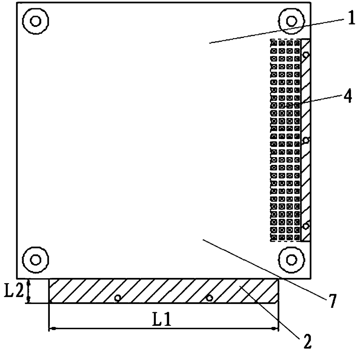
The invention provides a thermal control device for a stack assembly and relates to the technical field of satellite temperature control. The device comprises a circuit board, heat-radiating fins, a plug-in assembly, a connecting frame and heat-conducting copper bars. The heat-radiating fins are fixedly arranged the upper surface of on one side of the circuit board. The plug-in assembly is fixedly arranged on the upper surface of the circuit board and on a side surface adjacent to the heat-radiating fins. The heat-conducting copper bars are fixedly arranged on the outer side surface of the heat-radiating fins. The connecting frame is horizontally placed. The plurality of heat-conducting copper bars are longitudinally arranged in parallel. The plurality of heat-conducting copper bars are vertically and fixedly arranged on the fixed connecting frame. The circuit board comprises heat sink strips and a circuit board square board. The circuit board square board is of a square sheet structure. The heat sink strips are of a rectangular sheet-like structure. The heat sink strips are horizontally and fixedly arranged on the middle part of the side edge of the circuit board square board. The heat-radiating fins are fixedly arranged on the upper surface of the heat sink strips. According to the technical scheme of the thermal control method provided in the invention, the heat dissipation problem in the prior art that the heat consumption is mostly centralized on the stack assembly can be solved.

Description

technical field [0001] The invention relates to the technical field of satellite temperature control, in particular to a thermal control device for a stack assembly. Background technique [0002] With the development of microelectronics technology, especially the development of micro / nanotechnology represented by micro-electromechanical systems (MEMS) and micro-opto-electromechanical systems (MOEMS) in recent years, micro-satellites such as micro-satellites, nano-satellites, and pico-satellites Realization becomes possible. In recent years, a number of international research institutions have been engaged in the research of micro-nano satellites. Compared with other ordinary small satellites, they have significant advantages such as small mass, low design, manufacturing and launch costs. Navigation and many other fields have very broad application prospects. In order to achieve the weight reduction requirements of micro-nano satellites, multiple physically separated system...

Claims


Application Information

Patent Timeline
Patent Type & Authority Patents(China)
IPC IPC(8): H05K7/20
CPCH05K7/205
Inventor 徐志明房红军宁东坡
Owner AEROSPACE DONGFANGHONG SATELLITE
Learn More