
Bridge equipment

A technology for equipment and bridges, applied in the field of bridge equipment, can solve the problems of low production efficiency, time-consuming and laborious, complicated operation, etc., and achieve the effects of convenient operation, speeding up construction progress and improving construction efficiency.

Inactive Publication Date: 2017-09-05
叶利萍
View PDF0 Cites 9 Cited by
  • Summary
  • Abstract
  • Description
  • Claims
  • Application Information

AI Technical Summary

Problems solved by technology

[0002] In the process of bridge construction, a large number of steel plates and steel materials are needed. According to different needs, the steel plates and steel materials need to be processed. During the steel plate processing, the staff need to grind and drill the steel plates according to the requirements. Often used Drilling equipment and grinding equipment, when it is necessary to process steel plate grinding and drilling, since the drilling and grinding are performed on different machines, it is necessary to frequently switch the steel plate between the drilling equipment and the grinding equipment, when switching The steel plate needs to be clamped and positioned multiple times, the operation is complicated, time-consuming and labor-intensive, resulting in low production efficiency

Method used


Image

  • Bridge equipment
  • Bridge equipment
  • Bridge equipment

Examples


Embodiment Construction

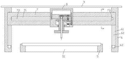
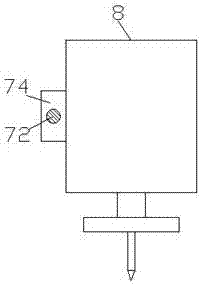
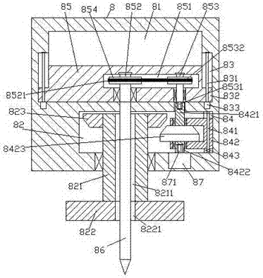
[0024] like Figure 1-Figure 5 As shown, a kind of bridge equipment of the present invention comprises a frame body composed of a pillar 6 and a top frame 7 and an underframe 5 arranged at the bottom of the frame body, a cover plate 9 is fixedly installed on the top of the pillar 6, and the The cover plate 9 is used to block dust, rain, etc., and the control member 8 is arranged in the frame, and the first cavity 81 is arranged inside the control member 8, and the inner walls of the left and right sides of the first cavity 81 are provided with The first sliding groove 83, the first screw rod 831 is arranged in the first sliding groove 83, the first sliding block 85 is slid and connected in the first cavity 81, and the first sliding block 85 under the first cavity 81 The control member 8 is provided with a second cavity 82, and the inner wall on the right side of the second cavity 82 is provided with a guide groove 84, and the guide groove 84 is provided with a guide rod 841, a...


PUM


Abstract

The invention discloses bridge equipment, which comprises a frame body and a bottom frame, wherein the frame body comprises support columns and a top frame; the bottom frame is arranged at the bottom of the frame body; a cover plate is fixedly arranged at the tops of the support columns; a control member is arranged in the frame body; a first hollow cavity is arranged in the control member; first sliding grooves are symmetrically arranged at the inner walls of the left side and the right side of the first hollow cavity; a first spiral rod is arranged in each first sliding groove; the inside of the first hollow cavity is connected with a first sliding block in a sliding fit manner; a second hollow cavity is arranged in the control member at the lower part of the first hollow cavity; a guide groove is formed in the inner side of the right side of the second hollow cavity; a guide rod is arranged in the guide groove; the guide rod is connected with a guide frame of which the left side extends into the second hollow cavity in a sliding fit manner; and a first cone pulley is arranged in the guide frame extending into the second hollow cavity. The bridge equipment is simple in structure and convenient to operate, the multi-purpose target can be achieved, equipment investment is reduced, steel plate clamping and locating frequency is reduced, and time and labor are saved, thereby improving the bridge construction efficiency and accelerating the construction progress.

Description

technical field [0001] The invention relates to the technical field of bridges, in particular to bridge equipment. Background technique [0002] In the process of bridge construction, a large number of steel plates and steel materials are needed. According to different needs, the steel plates and steel materials need to be processed. During the steel plate processing, the staff need to grind and drill the steel plates according to the requirements. Often used Drilling equipment and grinding equipment, when it is necessary to process steel plate grinding and drilling, since the drilling and grinding are performed on different machines, it is necessary to frequently switch the steel plate between the drilling equipment and the grinding equipment, when switching The steel plate needs to be clamped and positioned multiple times, and the operation is complicated, time-consuming and laborious, so that the production efficiency is not high. Contents of the invention [0003] The...

Claims


Application Information

Patent Timeline
Patent Type & Authority Applications(China)
IPC IPC(8): B23P23/04
CPCB23P23/04
Inventor 叶利萍
Owner 叶利萍
Learn More