Continuously variable transmission for bicycle

A technology of continuously variable transmissions and bicycles, applied in vehicle gearboxes, vehicle components, chain/belt transmissions, etc., can solve the problems of step-by-step speed reduction, low mechanical strength, and large friction, etc., to reduce torque mutations, The effect of compact mechanical structure and simple operation

Pending Publication Date: 2017-09-05
JINZHONG UNIV
View PDF17 Cites 0 Cited by
  • Summary
  • Abstract
  • Description
  • Claims
  • Application Information

AI Technical Summary

Problems solved by technology

The existing variable speed bicycle also has its disadvantages: in the process of shifting, it can only speed up and down step by step, cannot transition smoothly, cannot better adapt to different types of road conditions, and has a complicated structure and low mechanical strength; after the bicycle has been used for a period of time, the transmission It is very prone to failure, often unable to shift smoothly, or even improperly used, directly stuck (that is, the chain is stuck between the two shift discs) or the chain is dropped, and cannot shift when riding at high speed; the star wheel drive (CVP) in the shifter etc. rely on friction to work, in low-speed equipment such as bicycles, the friction is very large and cannot be transmitted accurately, and it is hardly used in bicycle events and trick shows

Method used


Image

  • Continuously variable transmission for bicycle
  • Continuously variable transmission for bicycle
  • Continuously variable transmission for bicycle

Examples


Embodiment Construction

[0028] The present invention will be further described below in conjunction with accompanying drawing:

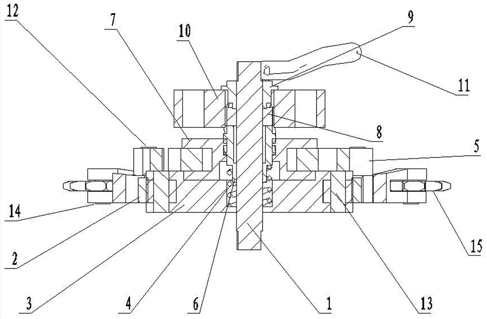
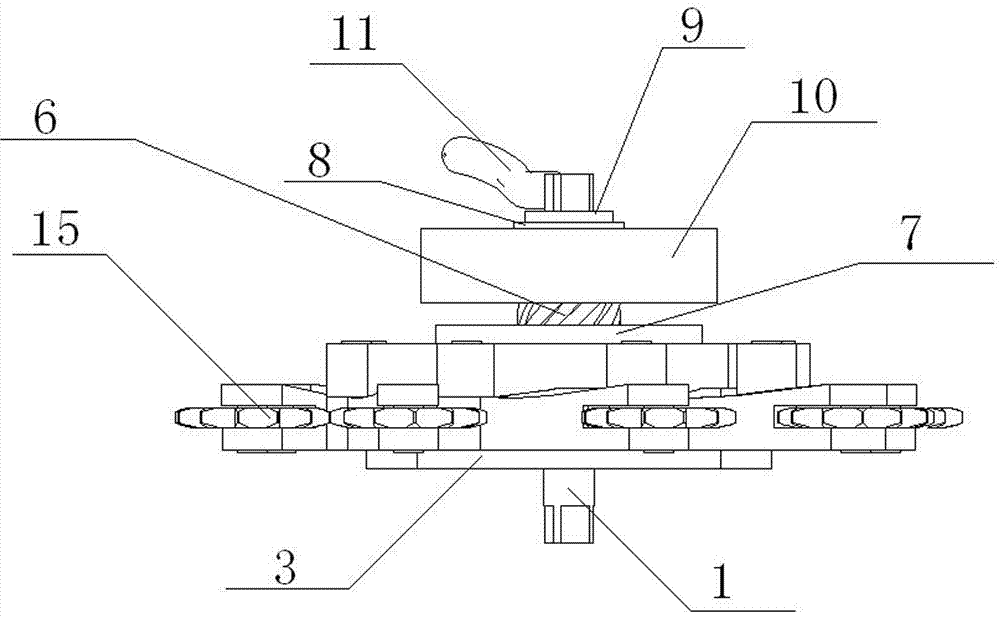
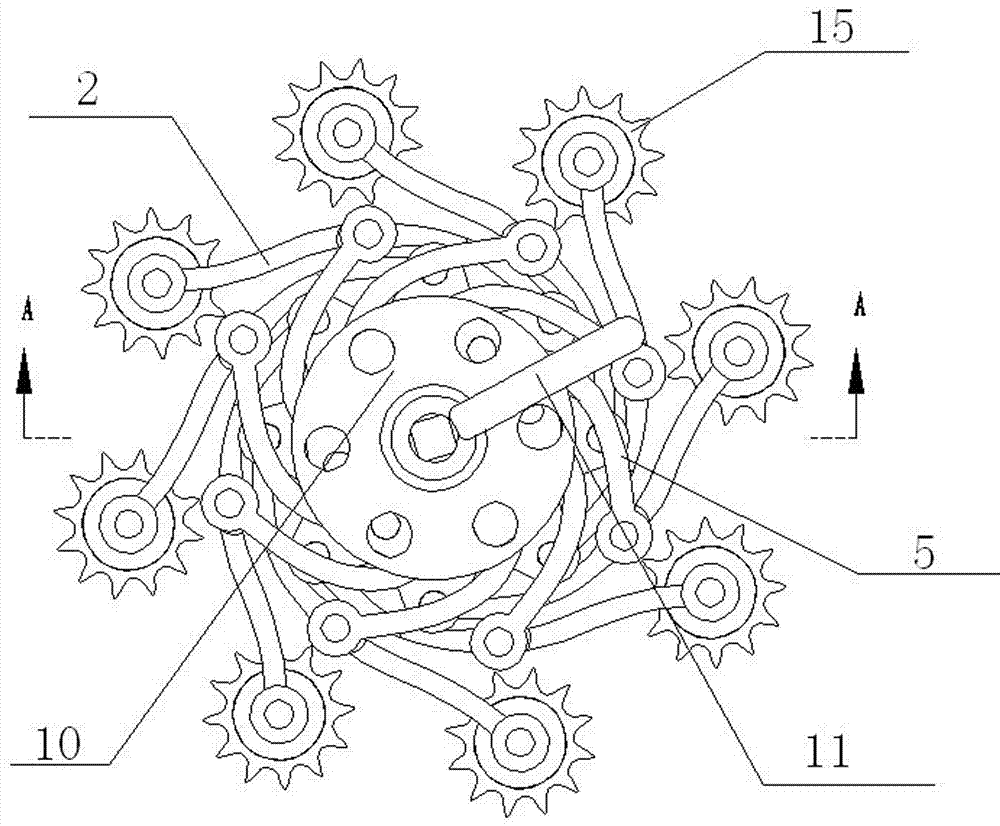
[0029] Such as Figures 1 to 4 As shown, a bicycle continuously variable transmission includes a rotating shaft 1, and the rotating shaft 1 sequentially passes through the circular hole in the center of the first transmission disc 3, the center of the spring 4, the circular hole in the center of the intermediate shaft 6, the first slip The round hole in the center of the gear 8, the round hole in the center of the second sliding gear 9, a spring 4 is arranged in the center hole of the first transmission disc 3, one end of the intermediate shaft 6 touches the spring 4, and the outer wall of the other end passes through Passing through the center of the second transmission disc 7, the other end touches one end of the first sliding gear 8, and the other end of the first sliding gear 8 touches one end of the second sliding gear 9, and the second sliding gear 9 The other end is...


PUM


Abstract

The invention discloses a continuously variable transmission for a bicycle. The continuously variable transmission comprises a rotating shaft; the rotating shaft successively passes through a first speed change disc, a spring, an intermediate shaft, a first sliding gear and a second sliding gear; the spring is arranged in the central circular hole of the first speed change disc; one end of the intermediate shaft is in contact with the spring; an outer wall of the other end passes through the center of a second speed change disc, and the other end is in contact with one end of the first sliding gear; the other end of the first sliding gear is in contact with one end of the second sliding gear; the other end of the second sliding gear is connected with a deflector rod; the first sliding gear is sleeved on an inner side of the central circular hole of the intermediate shaft; the edge of the first speed change disc is connected with a lantern ring at one end of a long flying rod; the other end of the long flying rod is connected with a flywheel through a pin rod; the central lantern ring of the long flying rod is connected with a lantern ring at one end of a short flying rod through the pin rod; and the edge of the second speed change disc is connected with a lantern ring at the other end of the short flying rod through the pin rod. By the continuously variable transmission for the bicycle, the problem that an existing transmission needs step-by-step speed change is solved.

Description

technical field [0001] The invention relates to a speed changer, in particular to a bicycle continuously variable speed changer. Background technique [0002] With the development of society, green travel is favored by people. For short-distance travel and cycling enthusiasts, a brisk shifter is usually selected as a tool. It has different transmission ratios and can adapt to more road conditions. It is very convenient for daily travel and weekend trips. The existing variable speed bicycle also has its disadvantages: in the process of shifting, it can only speed up and down step by step, cannot transition smoothly, cannot better adapt to different types of road conditions, and has a complicated structure and low mechanical strength; after the bicycle has been used for a period of time, the transmission It is very prone to failure, often unable to shift smoothly, or even improperly used, directly stuck (that is, the chain is stuck between the two shift discs) or the chain is...

Claims


Application Information

Patent Timeline
IPC IPC(8): B62M9/08
CPCB62M9/08
Inventor 刘慧玲李雪利孟志强加毅龙
Owner JINZHONG UNIV
Why Eureka
Try Eureka