Built-in disk rack

A built-in, disc technology, used in thin material processing, metal processing, winding strips, etc., can solve the problems of inconvenient loading and unloading, difficulty in adjusting the material shaft, etc., to improve efficiency and ensure stability.

Active Publication Date: 2017-09-05
XIAN AEROSPACE HUAYANG PRINTING & PACKAGING MACHINERY
View PDF16 Cites 4 Cited by
  • Summary
  • Abstract
  • Description
  • Claims
  • Application Information

AI Technical Summary

Problems solved by technology

[0003] The purpose of the present invention is to provide a built-in disc material rack, which solves the problems of difficulty in adjusting the material axis and inconvenient loading and unloading of the built-in disc material rack structure existing in the prior art

Method used


Image

  • Built-in disk rack
  • Built-in disk rack
  • Built-in disk rack

Examples


Embodiment Construction

[0035] The present invention will be described in detail below in conjunction with the accompanying drawings and specific embodiments.

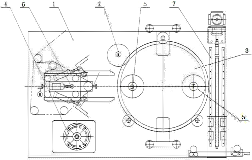
[0036] Such as figure 1 As shown, a built-in disc material rack includes two wall panels 1 arranged in parallel, a disc device 3 is embedded between the wall panels 1, and an S station and a T station are arranged in the disc device 3. Both the S station and the T station are equipped with a material shaft clamping mechanism 5; a cutting device 6 and a loading and unloading device 7 are also provided between the wall panels 1, and the cutting device 6 and the loading and unloading device 7 are distributed on the disc device 3 The two sides of the cutting knife device 6 are respectively provided with several guide rollers 9 above and below, and the disc device 3 is connected with a disc drive device 2, and the disc drive device 2 can drive the disc device 3 to rotate to realize the S station Receive and receive materials alternately with the ...


PUM


Abstract

The invention relates to a built-in disk rack. The built-in disk rack adopts the technical scheme that the built-in disk rack comprises two parallel wallboards, wherein a disk device is embedded between the wallboards, an S station and a T station are arranged in the disk device, and shaft clamping mechanisms are respectively arranged at the S station and the T station; a cutter device and a feeding and discharging device are further arranged between the wallboards, and the cutter device and a feeding and discharging device are distributed on both sides of the disk device; and a plurality of guide rollers are respectively arranged above and below the cutter device, a disk driving device is connected to the disk device, and the disk device can be driven to rotate by the disk driving device so as to alternately receive and collect materials by the S station and the T station. The problems of difficulty in adjusting shafts of the structure of an existing built-in disk rack and inconvenience in feeding and discharging in the prior art are solved.

Description

technical field [0001] The invention belongs to the field of printing machinery and relates to a built-in disc material rack. Background technique [0002] The current built-in disc material rack structure is usually composed of a wallboard, a disc, a disc driving device, a material shaft fixing device, a material shaft driving device, a cutting knife device and the like. In terms of fixing the material shaft, the existing chuck mechanism is used to fix the material shaft. There is a small gap between the chuck and the air expansion shaft. When running under high-speed conditions, the collision between the air expansion shaft and the chuck affects the The stability of the material roll rotation increases the noise and reduces the life of the chuck; the existing cone top structure is used to fix the material shaft, and the material roll must be tightened manually every time the material is loaded and unloaded, and manual adjustment of the material shaft is also required. Ope...

Claims


Application Information

Patent Timeline
Patent Type & Authority Applications(China)
IPC IPC(8): B65H19/12B65H19/30B26D1/06
CPCB26D1/065B65H19/126B65H19/30B65H2301/418
Inventor 陈龙黄小军吴国富刘宗建彭彪刘驰王力
Owner XIAN AEROSPACE HUAYANG PRINTING & PACKAGING MACHINERY
Why Eureka
Try Eureka