
Die assembling mechanism for turbine rotor with vibration attenuation plate, assembling mechanism and method

A turbine rotor and assembly mechanism technology, which is applied in the direction of machines/engines, blade support components, mechanical equipment, etc., can solve the problems of vibration damping sheet crushing, long time consumption, and affecting the quality of rotor assembly, so as to reduce the probability of damage and avoid The effect of hindering assembly and facilitating overall transfer

Active Publication Date: 2017-09-05
CHINA HANGFA SOUTH IND CO LTD
View PDF4 Cites 6 Cited by
  • Summary
  • Abstract
  • Description
  • Claims
  • Application Information

AI Technical Summary

Problems solved by technology

[0004] The invention provides an upper mold mechanism, an assembly mechanism and a method for a turbine rotor with vibration damping plates, to solve the problem of the existing assembly method of turbine rotors with vibration damping plates, the assembly process takes a long time; The technical problem that the vibrating plate is crushed and affects the quality of the rotor assembly

Method used


Image

  • Die assembling mechanism for turbine rotor with vibration attenuation plate, assembling mechanism and method
  • Die assembling mechanism for turbine rotor with vibration attenuation plate, assembling mechanism and method

Examples


Embodiment Construction

[0023] The embodiments of the present invention will be described in detail below with reference to the accompanying drawings, but the present invention can be implemented in various ways defined and covered below.

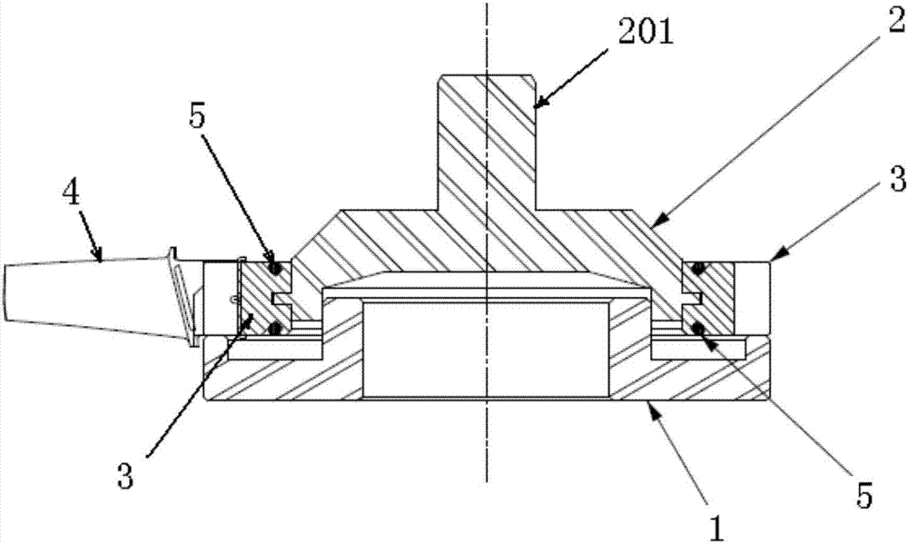
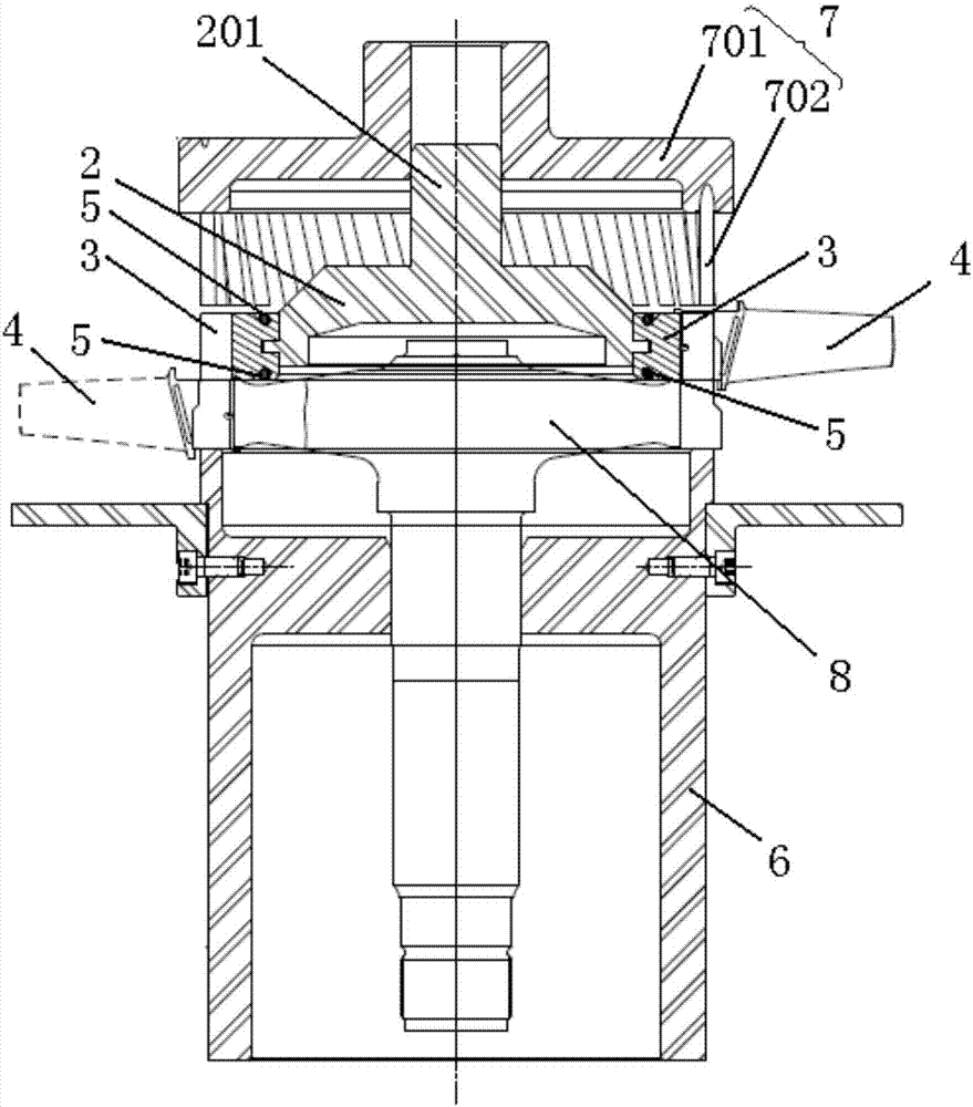
[0024] figure 1 It is a structural schematic diagram of an upper mold mechanism for assembling a turbine rotor with damping plates according to a preferred embodiment of the present invention; figure 2 It is a structural schematic diagram of an assembly mechanism for a turbine rotor with damping plates in a preferred embodiment of the present invention.

[0025] Such as figure 1 As shown, the upper mold mechanism for the assembly of turbine rotors with damping plates in this embodiment includes a bottom mold support 1 for forming a bottom support and an inner core support 2 for forming a radial support. The bottom mold The support 1 and the inner core support 2 are mutually fixed and positioned by nesting, and the side wall of the inner core support 2 is provid...


PUM


Abstract

The invention discloses a die assembling mechanism for a turbine rotor with a vibration attenuation plate, an assembling mechanism and a method. The die assembling mechanism for the turbine rotor with the vibration attenuation plate comprises a bottom die support for forming bottom support and an inner core support for forming radial support. The bottom die support and the inner core support are fixed and positioned in an embedded manner. A plurality of movable process mortise units which are used for enabling turbine rotor vane tenon teeth to be vertically inserted and assembled and move within a constraint range to assemble the vibration attenuation plate to the part between adjacent turbine rotor vanes. The multiple movable process mortise units are distributed in an adjoining manner in the circumferential direction of the inner core support, and the movable process mortise units and the turbine rotor vanes are distributed in a one-to-one corresponding manner. The circumferential dimensions of the movable process mortise units are matched with those of the turbine rotor vanes, and thus the assembled turbine rotor vanes are distributed in an adjoining manner in the circumferential direction of the inner core support. The overall transferring of a preassembled structure is facilitated, and the assembling efficiency of the turbine rotor is improved.

Description

technical field [0001] The invention relates to the technical field of aero-engine assembly, in particular to an upper mold mechanism for assembling a turbine rotor with damping plates. In addition, the present invention also relates to an assembly mechanism comprising the above-mentioned upper mold mechanism for assembling a turbine rotor with damping plates. In addition, the present invention also relates to an assembly method comprising the above-mentioned upper mold mechanism and assembly mechanism for assembling a turbine rotor with damping plates. Background technique [0002] In aero-engines, there is a turbine rotor with damping plates to reduce the damage caused by vibration to the turbine rotor. The structure of the turbine rotor with damping plate is mainly composed of blades, turbine discs and damping plates. The blades and turbine discs are connected by tenons, and the damping plates are installed in the bosses between the edge plates of adjacent blades. Since...

Claims


Application Information

Patent Timeline
Patent Type & Authority Applications(China)
IPC IPC(8): F01D5/30B25B27/02
CPCB25B27/02F01D5/30
Inventor 张为吴剑杨世春
Owner CHINA HANGFA SOUTH IND CO LTD
Learn More