Signal sending device, carrier phase recovery device and method
A signal transmission device and signal technology, applied in the field of communication, can solve the problems of laser phase noise sensitivity, limiting system transmission efficiency, bit errors, etc., and achieve the effect of reducing redundancy and low computational complexity
- Summary
- Abstract
- Description
- Claims
- Application Information
AI Technical Summary
Problems solved by technology
Method used
Image


Examples
Embodiment 1
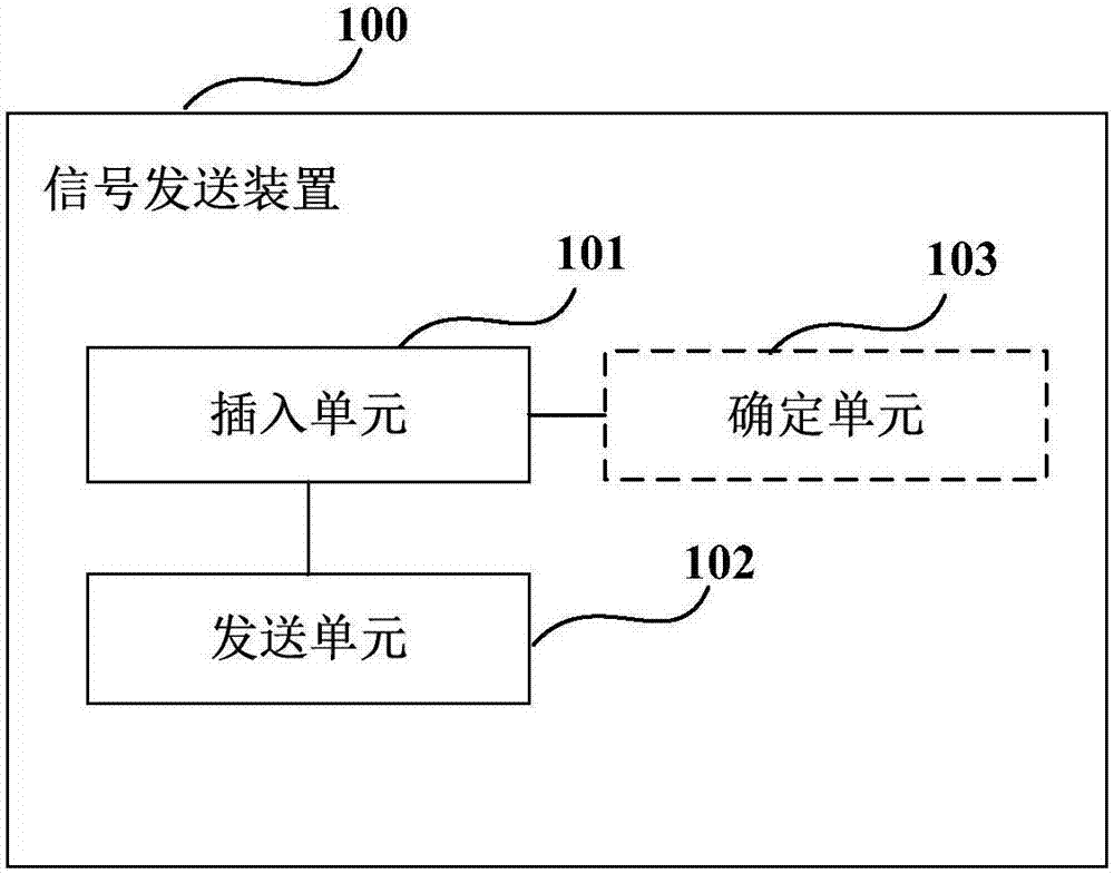
[0046] figure 1 It is a schematic diagram of the signal sending device according to Embodiment 1 of the present invention. Such as figure 1 As shown, the device 100 includes:
[0047] Insertion unit 101, configured to insert at least one amplitude-variable phase modulation signal into the data modulation signal for carrier phase recovery at the receiving end;
[0048] The sending unit 102 is configured to send a sending signal formed by inserting the phase modulation signal into the data modulation signal.
[0049] It can be seen from the above embodiments that by inserting a phase modulation signal with variable amplitude into the data modulation signal, the carrier phase recovery of the received signal is performed at the receiving end according to the phase modulation signal, which can be applied to communication systems of various modulation formats and is compatible with existing Some communication systems are compatible and have lower computational complexity. In add...
Embodiment 2
[0076] The embodiment of the present invention also provides a carrier phase recovery device, Figure 14 It is a schematic diagram of a carrier phase recovery device according to Embodiment 2 of the present invention. Such as Figure 14 As shown, the device 1400 includes:
[0077] The extraction unit 1401 is configured to extract a phase modulation signal in the received signal, wherein the phase modulation signal is a phase modulation signal with variable amplitude inserted in the data modulation signal sent by the transmitting end;
[0078] An estimation unit 1402, configured to estimate the phase noise of the received signal according to the phase modulation signal in the received signal;
[0079] The compensation unit 1403 is configured to perform phase compensation on the received signal according to the phase noise of the received signal.
[0080] It can be seen from the above embodiments that by inserting a phase modulation signal with variable amplitude into the dat...
Embodiment 3
[0105] The embodiment of the present invention also provides a transmitter, Figure 18 is a schematic diagram of the transmitter according to Embodiment 3 of the present invention. Such as Figure 18 As shown, the transmitter 1800 includes a signal sending device 1801, the structure and function of the signal sending device 1801 are the same as those described in Embodiment 1, and will not be repeated here.
[0106] Figure 19 It is a schematic block diagram of the system configuration of the transmitter according to Embodiment 3 of the present invention. Such as Figure 19 As shown, the transmitter 1900 includes: an insertion unit 1901, a sending unit 1902, a digital-to-analog conversion unit 1903, and an optical modulator unit 1904, wherein:
[0107] The insertion unit 1901 inserts at least one amplitude-variable phase modulation signal into the data modulation signal for carrier phase recovery at the receiving end; the transmission unit 1902 transmits the transmission s...
PUM
 Abstract
Description
Claims
Application Information
 - R&D
- Intellectual Property
- Life Sciences
- Materials
- Tech Scout
- Unparalleled Data Quality
- Higher Quality Content
- 60% Fewer Hallucinations
Browse by: Latest US Patents, China's latest patents, Technical Efficacy Thesaurus, Application Domain, Technology Topic, Popular Technical Reports.
© 2025 PatSnap. All rights reserved.Legal|Privacy policy|Modern Slavery Act Transparency Statement|Sitemap|About US| Contact US: help@patsnap.com