Moving iron receiver with novel magnetic conduction structure

A receiver and magnetic guide technology, applied in the directions of loudspeakers, sensors, electrical components, etc., can solve the problems of complicated assembly process of magnetic circuit system and difficult processing of magnetic yokes, and is conducive to automated large-scale production, simplified product design, The effect of improving product performance

Pending Publication Date: 2017-09-05
SUZHOU E AUDIO ELECTRONICS
View PDF11 Cites 14 Cited by
  • Summary
  • Abstract
  • Description
  • Claims
  • Application Information

AI Technical Summary

Problems solved by technology

At present, the design of the magnetic yoke is basically a "mouth" shape to form a magnetic circuit. This design makes it difficult to process the magnetic yoke and also complicates the assembly process of the magnetic circuit system.

Method used


Image

  • Moving iron receiver with novel magnetic conduction structure
  • Moving iron receiver with novel magnetic conduction structure
  • Moving iron receiver with novel magnetic conduction structure

Examples


Embodiment 1

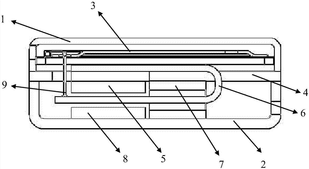
[0023] like figure 1 and figure 2 As shown, a moving iron receiver with a new magnetic permeation structure, including the shell formed by the upper shell 1 and the lower shell 2, the diaphragm 3 is fixed in the upper shell 1 and the inner space of the shell is divided into a front cavity and a rear cavity Cavity, the space between the diaphragm 3 and the upper shell 1 is the front cavity, the space between the diaphragm 3 and the lower shell 2 is the rear cavity, the reed, the magnetic plate, the upper magnet, the coil, the driving rod, the lower magnet.

[0024] Specifically, the magnetic guide plate 4 is in the shape of a sheet and is arranged in the rear cavity, the edges of the magnetic guide plate are fixed to the upper and lower housings, and the upper surface of the upper magnet 5 and the lower surface of the magnetic guide plate 4 are fixed together by welding or bonding. . The U-shaped reed 6 includes a fixed portion and a vibrating portion, the fixed portion of ...

Embodiment 2

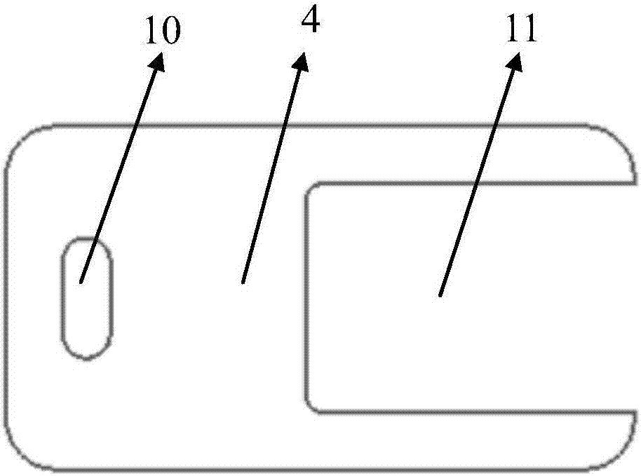
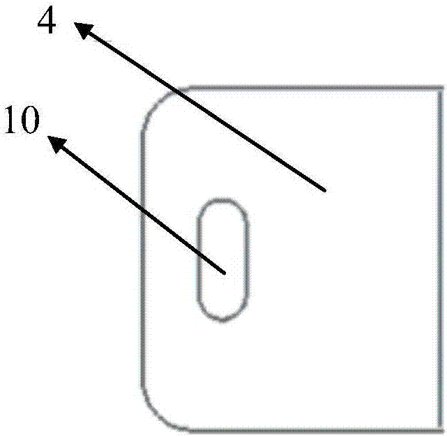
[0029] The structure is similar to that of Embodiment 1, the difference is that the magnetic guide plate 4 is a half-piece, the lower housing 2 has a step surface 12 matched with the magnetic guide plate, and the upper housing, the magnetic guide plate and the lower housing form a closed shell, such as image 3 , 4 As shown, the structure is more simplified, and the use of magnetic plate materials is saved.

Embodiment 3

[0031] The structure is similar to Embodiment 1, the difference is that the magnetic guide plate 4 is a small piece, that is, it is only arranged on the fixed part of the U-shaped reed 6 and corresponds to the upper magnet and the lower magnet, and the middle part of the lower housing has a magnetic guide plate. The groove 13, the upper shell, the magnetic guide plate, and the lower shell form a closed shell, such as Figure 5 , 6 As shown, the structure is more simplified.


PUM


Abstract

The invention discloses a moving iron receiver with a novel magnetic conduction structure. The moving iron receiver comprises a shell, and a vibrating diaphragm, a reed, a magnetic conduction plate, an upper magnet, a coil, a driving rod and a lower magnet arranged in the shell, wherein the shell consists of an upper shell and a lower shell, the vibrating diaphragm is arranged in the upper shell and divides the inner space of the shell into a front cavity and a rear cavity, the magnetic conduction plate is in a sheet shape and is arranged in the rear cavity, and the edge of the magnetic conduction plate is fixed with the upper shell and the lower shell. According to the moving iron receiver disclosed by the invention, an existing square magnet yoke structure is replaced by the sheet-like magnetic conduction plate, and thus the product design can be simplified, the product performance can also be improved, and the automatic mass production can be facilitated.

Description

technical field [0001] The invention relates to a moving iron receiver with a novel magnetic conduction structure. Background technique [0002] The moving iron receiver, also known as the balanced armature receiver, is a highly efficient miniature electroacoustic transducer. Widely used in earphones, hearing aids and wearable electronic devices. Its working principle: Under the action of alternating current, the reed in the magnetic field will move up and down, so that the driving rod drives the diaphragm to agitate the air up and down to make a sound. [0003] The magnetic circuit system of a traditional receiver includes: a magnet, a yoke, a reed and a coil. Usually, one end of the U-shaped reed is welded to the yoke, and the other end is in the magnetic field of the upper and lower magnets. At present, the design of the magnetic yoke is basically a "mouth" shape to form a magnetic circuit. This design makes it difficult to process the magnetic yoke and also complicate...

Claims


Application Information

Patent Timeline
Patent Type & Authority Applications(China)
IPC IPC(8): H04R11/02
CPCH04R11/02H04R2400/11
Inventor 薛洪明张春刚刘洋
Owner SUZHOU E AUDIO ELECTRONICS
Why Eureka
Try Eureka