Short-stress-path rolling mill and elimination method for threaded clearance of short-stress-path rolling mill
A technology of short stress lines and thread gaps, applied in metal rolling stands, metal rolling mill stands, metal rolling, etc., can solve the problems of eliminating the effect of gaps, affecting rolling precision of rolling mills, troublesome installation and replacement, etc. , to prolong the service life, improve the elimination effect, and solve the effect of fatigue failure
- Summary
- Abstract
- Description
- Claims
- Application Information
AI Technical Summary
Problems solved by technology
Method used
Image
Examples
Embodiment 1
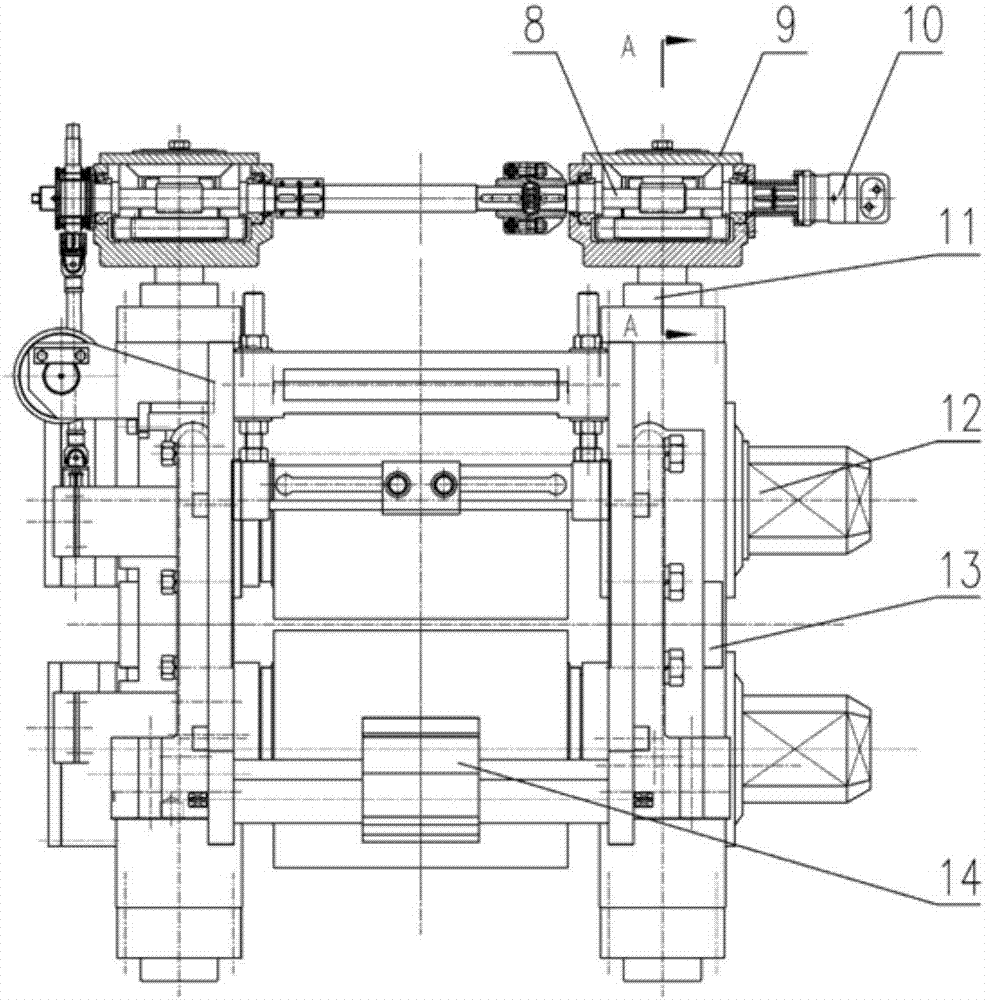
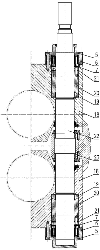
[0044] Such as figure 1 , image 3 As shown, a short stress line rolling mill in this embodiment includes a frame 13, a tie rod assembly 11, a roll assembly 12, a guide beam assembly 14 and a roll gap adjustment device 9, wherein the frame 13 is fixed on the mobile base, the pull rod assembly 11 is fixed on the frame 13 through the guide sleeve 23, and the bearing housing 18 of the roller assembly 12 is connected to the symmetrically arranged pull rods 22. The upper and lower roll chocks 18 of the roll assembly 12 are all processed with assembly holes for the passage of the pull rod 22, and the copper nut 20 and the auxiliary nut 21 threaded with the pull rod 22 are installed in the assembly hole, and the copper nut 20 is connected with the pull rod 22. The auxiliary nut 21 is fixedly connected by a pin; the pull rod 22 is also provided with an end cover 5, the end cover 5 is fixedly connected with the bearing seat 18, and a balance device for eliminating thread gap is instal...
Embodiment 3
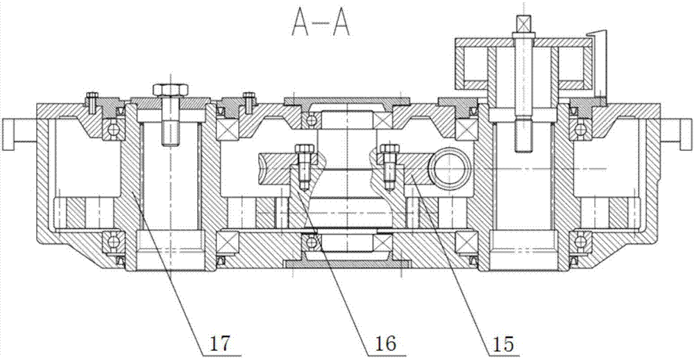
[0059] to combine Figure 1-Figure 3 , a short stress line rolling mill of this embodiment, its structure is basically the same as that of Embodiment 2, the difference is that a spherical pad 19 is provided between the copper nut 20 and the bearing seat 18 . The roll gap adjusting device 9 of the present embodiment comprises a hydraulic motor 10, a worm 8, a worm wheel 15, a gear shaft I 16 and a gear shaft II 17, wherein the worm 8 is meshed with the worm wheel 15, and the worm 8 is driven by the hydraulic motor 10 Connected, the gear shaft I16 is installed on the worm wheel 15, the gear shaft I16 and the gear shaft II17 are connected through matching gear transmission, and the gear shaft II17 and the pull rod 22 are connected by a key. The hydraulic motor 10 is used as power to drive the worm 8 to rotate, and the worm 8 drives the worm gear 15 to rotate, and the worm gear 15 drives the gear shaft II 17 to rotate through the gear shaft I 16 and the mating gear. The inner hol...
PUM
 Abstract
Description
Claims
Application Information
 - R&D
- Intellectual Property
- Life Sciences
- Materials
- Tech Scout
- Unparalleled Data Quality
- Higher Quality Content
- 60% Fewer Hallucinations
Browse by: Latest US Patents, China's latest patents, Technical Efficacy Thesaurus, Application Domain, Technology Topic, Popular Technical Reports.
© 2025 PatSnap. All rights reserved.Legal|Privacy policy|Modern Slavery Act Transparency Statement|Sitemap|About US| Contact US: help@patsnap.com


