
Production machining equipment of color steel tiles

A technology of processing equipment and color steel tiles, which is applied in the direction of metal processing equipment, metal processing, manufacturing tools, etc., can solve the problems that the quality and consistency of processing are difficult to guarantee, the processing pressure cannot be controlled, and the safety performance of use needs to be improved. , to achieve the effect of improving safety performance, novel structure and improving service life

Active Publication Date: 2017-09-08
颍上县双盛金属制品股份有限公司
View PDF5 Cites 2 Cited by
  • Summary
  • Abstract
  • Description
  • Claims
  • Application Information

AI Technical Summary

Problems solved by technology

[0002] Color steel tile, also known as color profiled tile, is a profiled plate made of color-coated steel plates that is rolled and cold-bent into various wave shapes. It is suitable for industrial and civil buildings, warehouses, special buildings, and long-span steel structures. The roof, wall, and interior and exterior wall decoration of the house have the characteristics of light weight, high strength, rich color, convenient and quick construction, earthquake resistance, fire prevention, rain resistance, long life, and maintenance-free. The steel tile processing equipment is unscientific in design, and the pressing process of the equipment is not smooth enough. The driving module often bears the gravity of the pressing module, which reduces the service life of the equipment. The entire processing process requires manual intervention, low degree of automation, time-consuming and laborious, and low processing efficiency. , the processing pressure cannot be controlled, the quality and consistency of the processing are difficult to guarantee, and the safety performance of the equipment needs to be improved.

Method used


Image

  • Production machining equipment of color steel tiles

Examples


Embodiment Construction

[0016] The technical solution of this patent will be further described in detail below in conjunction with specific embodiments.

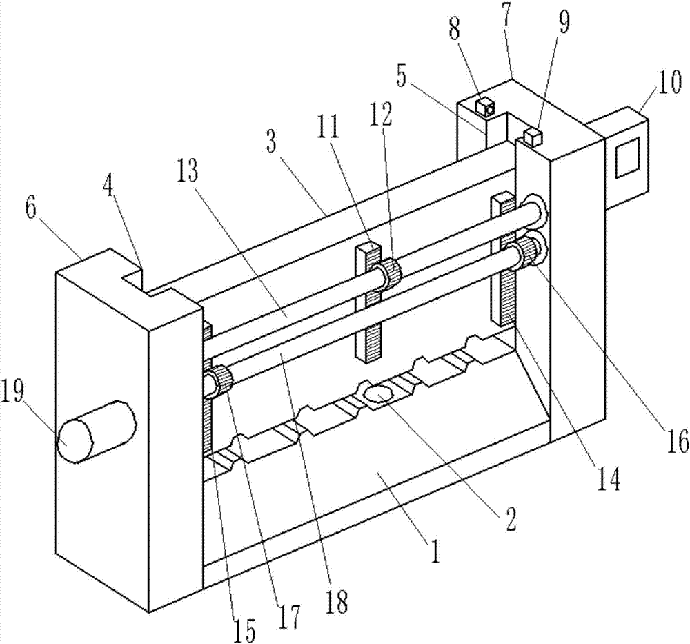
[0017] see figure 1 , in an embodiment of the present invention, a color steel tile production and processing equipment, including a base 1, a pressure sensor 2, a movable platen 3, a left chute 4, a right chute 5, a left bracket 6, a right bracket 7, and a laser emitter 8 , laser receiver 9, control module 10, driven rack 11, driven wheel 12, driven shaft 13, right drive rack 14, left drive rack 15, right drive wheel 16, left drive wheel 17, drive shaft 18 and a motor 19, a pressure sensor 2 is installed in the middle of the upper end surface of the base 1, a movable platen 3 is arranged above the base 1, the left end surface of the movable platen 3 is slidably connected with the left chute 4, and the right end surface of the movable platen 3 Slidingly connected with the right chute 5, the left chute 4 is arranged on the middle part of the right ...


PUM


Abstract

The invention discloses production machining equipment of color steel tiles. The equipment comprises a base, a pressure sensor, a movable pressing plate, a left chute, a right chute, a left support, a right support, a laser transmitter, a laser receiver, a control module, a driven rack, a driven wheel, a driven rotating shaft, a right driving rack, a left driving rack, a right driving wheel, a left driving wheel, a driving shaft and a motor. The equipment is novel in structure and scientific in design; the driven rack is mounted in the middle of the front end surface of the movable pressing plate and is meshed with the driven wheel to realize constant-speed motion of the movable pressing plate; moreover, the gravity of the sliding pressing plate is borne, so that axial force of the motor is reduced, the service life of the equipment is greatly prolonged, and manual intervention in a whole machining process is not needed, the automation degree is high, the machining efficiency is improved, the pressure sensor is increased, controlled machining pressure is realized, and the quality and consistence of the machining are improved; due to the arrangement of the laser transmitter and the laser receiver, the using security performance of the equipment are further improved.

Description

technical field [0001] The invention relates to the technical field of plate forming and processing, in particular to a production and processing equipment for color steel tiles. Background technique [0002] Color steel tile, also known as color profiled tile, is a profiled plate made of color-coated steel plate that is rolled and cold-bent into various wave shapes. It is suitable for industrial and civil buildings, warehouses, special buildings, and long-span steel structures. The roof, wall, and interior and exterior wall decoration of the house have the characteristics of light weight, high strength, rich color, convenient and quick construction, earthquake resistance, fire prevention, rain resistance, long life, and maintenance-free. The steel tile processing equipment is unscientific in design, and the pressing process of the equipment is not smooth enough. The driving module often bears the gravity of the pressing module, which reduces the service life of the equipmen...

Claims


Application Information

Patent Timeline
Patent Type & Authority Applications(China)
IPC IPC(8): B21D13/02B21C51/00
CPCB21C51/00B21D13/02
Inventor 张代玉
Owner 颍上县双盛金属制品股份有限公司
Learn More