Belt type loading device applied to numerical-control circular sawing machine

A technology of belt-type and circular sawing machines, which is applied in sawing machine devices, metal sawing equipment, metal processing, etc. It can solve problems such as the inability to hoist a whole bundle, the inability to realize double-root cutting, and the inability to clamp, etc., to achieve Effects of reducing frictional resistance, saving cutting time and cost, and widening the range of shapes

Active Publication Date: 2017-09-08
SHANGHAI HANHONG PRECISION MACHINERY
View PDF8 Cites 15 Cited by
  • Summary
  • Abstract
  • Description
  • Claims
  • Application Information

AI Technical Summary

Problems solved by technology

[0002] The circular saw machines currently on the market cannot be hoisted to the loading rack in whole bundles during the process of feeding the bars. Generally, only about a dozen pieces can be hoisted at a time, and they are manually arranged on the loading rack. After that, reload
Moreover, the circular saw machine loading racks currently on the market cannot achieve double cutting when cutting fine materials, because the two bars will cross together when feeding, and there is no way to clamp them.

Method used


Image

  • Belt type loading device applied to numerical-control circular sawing machine
  • Belt type loading device applied to numerical-control circular sawing machine
  • Belt type loading device applied to numerical-control circular sawing machine

Examples


Embodiment Construction

[0036] The following structural drawings further illustrate the present invention.

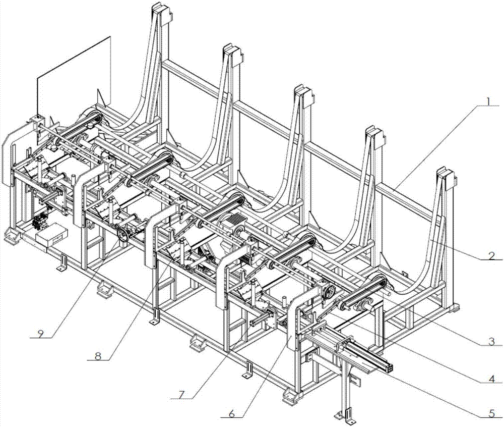
[0037] The belt type feeding mechanism such as figure 1 As shown, it mainly consists of a loading rack base 1, a pulley assembly 2, a chain conveying assembly 3, an inclined support plate 4, a cylinder pushing assembly 5, a stopper adjustment assembly 6, a clamping cylinder assembly 7, an overturning cylinder assembly 8 and a bar Diameter adjustment assembly 9 etc. constitute.

[0038] Hoist the whole bundle of bars on the belt of the pulley assembly 2, and tighten the belt through the parallel shaft reduction motor on the pulley assembly 2, so that the bars roll down to the chain of the chain conveying assembly 3, and the small deceleration of the chain conveying assembly 3 The motor drives the bar to move to the inclined support plate 4, adjust the height of the block of the stop adjustment assembly 6 according to the diameter of the bar, control the bars to pass one by one, and then adjust...


PUM


Abstract

The invention provides a belt type loading device applied to a numerical-control circular sawing machine. The belt type loading device comprises a loading frame basal body, a belt wheel assembly, a chain conveying assembly, an inclined supporting plate, an air cylinder pushing assembly, a baffle regulating assembly, a clamping oil cylinder assembly, a turnover oil cylinder assembly and a rod diameter regulating assembly. A whole bundle of rods is lifted onto a belt of the belt wheel assembly, and the belt is tightened, so that the rods drop onto a chain of the chain conveying assembly; the chain conveying assembly drives the rods to move to the inclined supporting plate; the height position of a baffle block of the baffle regulating assembly is regulated according to the diameters of the rods, and the rods are controlled to pass through one by one, then, the rods are turned over to a U-shaped plate of the loading frame basal frame through a turnover oil cylinder of the turnover oil cylinder assembly, the air cylinder pushing assembly pushes materials forwards, the clamping oil cylinder assembly clamps rods, the workbench of a machine head part of a main machine retreats to the origin point to clamp the rods, the clamping oil cylinder assembly of the loading mechanism is loosened, and the workbench clamps the rods to forwards feed to complete cutting. The whole process is automatically controlled, and manual control is not needed.

Description

technical field [0001] The invention relates to a numerically controlled circular saw, in particular to a belt-type feeding device applied to a numerically controlled circular saw. Background technique [0002] The circular saw machines currently on the market cannot be hoisted to the loading rack in whole bundles during the process of feeding the bars. Generally, only about a dozen pieces can be hoisted at a time, and they are manually arranged on the loading rack. After that, reload. Moreover, the circular saw machine loading racks on the market cannot realize double cutting when cutting fine materials, because the two bars will cross together when feeding, and there is no way to clamp them. Contents of the invention [0003] Aiming at the problems existing in the prior art, the present invention provides a belt-type feeding device applied to a CNC circular saw machine, which can hoist a whole bundle of bars onto the belt of the feeding rack, and realize automatic feedi...

Claims


Application Information

Patent Timeline
Patent Type & Authority Applications(China)
IPC IPC(8): B23D47/04B23Q7/00
CPCB23D47/042B23Q7/00
Inventor 刘伟贺贤汉郡司拓
Owner SHANGHAI HANHONG PRECISION MACHINERY
Why Eureka
Try Eureka