
Step shaft cylindrical plane lathe cutting and radial hole drilling clamp

A technology of external turning and radial drilling, which is applied in the field of clamping devices, can solve the problems that affect the processing quality, precision, efficiency, can not guarantee the symmetry of the hole, and the quality of the milling surface is not good, so as to achieve a simple structure , good elasticity, easy and safe production effect

Pending Publication Date: 2017-09-08
AVIC STANDARD PARTS MFG
View PDF10 Cites 1 Cited by
  • Summary
  • Abstract
  • Description
  • Claims
  • Application Information

AI Technical Summary

Problems solved by technology

In the prior art, the milling machine is used to process the plane parallel to the axis on the large outer circle of the stepped shaft, and the milling is carried out by clamping the two ends with a special fixture or clamping the two ends with a vise. The quality of the milling surface is poor and the speed is slow. , large burr
Drilling radial holes is processed on a drilling machine with a special drilling tool clamping. The clamping is slow and the burrs are large. Affected processing quality, precision, efficiency, etc.

Method used


Image

  • Step shaft cylindrical plane lathe cutting and radial hole drilling clamp
  • Step shaft cylindrical plane lathe cutting and radial hole drilling clamp
  • Step shaft cylindrical plane lathe cutting and radial hole drilling clamp

Examples


Embodiment Construction

[0024] In the following, with reference to the accompanying drawings and preferred embodiments, the specific implementation, structure, features and functions of the jig for turning the outer circle of the stepped shaft and radial drilling according to the present invention will be described in detail as follows.

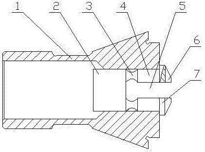
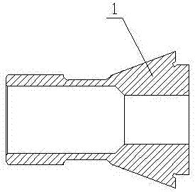
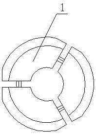
[0025] see Figure 1 to Figure 6 , the fixture of the present invention for turning the outer circle of the step shaft and radially drilling, including a circlip 1 and a fixture body 2, wherein: the fixture body 2 is nested inside the circlip 1, and the fixture body 2 is connected by a connecting body 3 The fixture petal body 4, the installation groove 5 is formed between the fixture petal bodies 4, the fixture petal body 4 is connected with the positioning block 7, the front part of the positioning block 7 is provided with an end face cavity 6, and the positioning block 7 is placed outside the end face of the circlip 1 . A stepped shaft positioning surface is form...


PUM


Abstract

The invention discloses a step shaft cylindrical plane lathe cutting and radial hole drilling clamp. The step shaft cylindrical plane lathe cutting and radial hole drilling clamp comprises a snap spring (1) and a clamp body (2) and is characterized in that the clamp body (2) is embedded into the snap spring (1), the clamp body (2) is connected with clamp clacks (4) through connecting bodies (3), installing grooves (5) are formed between the clamp clacks (4), the clamp clacks (4) are connected with positioning blocks (7), end face cavities (6) are formed in the front portions of the positioning blocks (7), the positioning blocks (7) are arranged on the outer sides of the end face of the snap spring (1), and step shaft positioning faces are formed between the clamp clacks (4) and the positioning blocks (7); and the snap spring (1) and the positioning blocks (7) are positioned through the step shaft positioning faces, and each installing groove (5) is defined by two clamp clacks (4) at the upper portion and the lower portion correspondingly. The step shaft cylindrical plane lathe cutting and radial hole drilling clamp is simple in structure, high quality, economical, convenient to operate, efficient, reliable and suitable for use and popularization in step shaft cylindrical plane lathe cutting and radial hole drilling.

Description

technical field [0001] The invention belongs to the technical field of clamping devices, and in particular relates to a clamp for turning planes and radially drilling the outer circle of a stepped shaft. Background technique [0002] For stepped shafts, it is a very common operation to turn flat, radial holes in their outer circumference. In the prior art, the milling machine is used to process the plane parallel to the axis on the large outer circle of the stepped shaft, and the milling is carried out by clamping the two ends with a special fixture or clamping the two ends with a vise. The quality of the milling surface is poor and the speed is slow. , Large burrs. Drilling radial holes is processed on a drilling machine with a special drilling tool clamping. The clamping is slow and the burrs are large. Affected processing quality, precision, efficiency and so on. Contents of the invention [0003] The object of the present invention is to overcome the above-mentioned...

Claims


Application Information

Patent Timeline
Patent Type & Authority Applications(China)
IPC IPC(8): B23Q3/12
CPCB23Q3/12
Inventor 陈菊
Owner AVIC STANDARD PARTS MFG
Learn More