Bearing bush type gearbox elastic supporting automatic ejection die and automatic ejection method thereof

An elastic support and automatic demoulding technology, applied in the field of metal rubber product manufacturing, can solve the problems of high labor intensity, low product qualification rate, product surface damage, etc., to reduce labor intensity, simple demoulding operation, and improve product quality Effect

Active Publication Date: 2017-09-08
ZHUZHOU TIMES NEW MATERIALS TECH
View PDF4 Cites 6 Cited by
  • Summary
  • Abstract
  • Description
  • Claims
  • Application Information

AI Technical Summary

Problems solved by technology

[0003] 1. The operation is labor-intensive, and the mold is manually installed and demolded, and a crane, crowbar, and mallet are required. The product needs to be transported to the demoulding core on a special hydraulic press, which takes a long time and is labor-intensive;
[0004] 2. The pass rate of the product is low, and the demoulding process relies on manual beating operations, which can easily cause damage to the product surface;
[0005] 3. The production efficiency is low, the mold loading and demoulding operation steps are numerous, the time is long, and the hydraulic press is required, the production efficiency is low

Method used


Image

  • Bearing bush type gearbox elastic supporting automatic ejection die and automatic ejection method thereof
  • Bearing bush type gearbox elastic supporting automatic ejection die and automatic ejection method thereof
  • Bearing bush type gearbox elastic supporting automatic ejection die and automatic ejection method thereof

Examples


Embodiment Construction

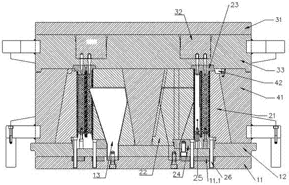
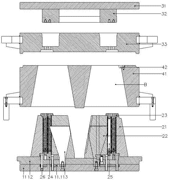
[0043] Attached below Figures 2 to 9 Embodiments of the present invention are described in detail.

[0044]The bearing pad type gearbox elastically supports the automatic demoulding mold, including a bottom mold assembly 1, a lower mold assembly 2 placed on the bottom mold assembly, an upper mold assembly 3 placed on the lower mold assembly 2 and a bottom mold assembly placed on the bottom mold assembly. Between the mold assembly 1 and the upper mold assembly 3, the middle mold assembly 4 for clamping the lower mold assembly, the upper mold assembly 3 includes a horizontally arranged top plate 31, a rubber injection plug 32 fixed below the top plate 31 and The glue injection cylinder 33 matched with the glue injection plug 32 is characterized in that the bottom mold assembly 1 includes a horizontal bottom plate 11, a supporting plate 12 placed on the bottom plate 11, and a vertically arranged and fixed bottom plate 11. The lower mold assembly 2 includes an outer petal mold 2...


PUM


Abstract

The invention discloses a bearing bush type gearbox elastic supporting automatic ejection die and an automatic ejection method thereof. The bearing bush type gearbox elastic supporting automatic ejection die comprises a bottom die assembly, a lower die assembly, an upper die assembly and a middle die assembly. The upper die assembly comprises a top plate, a glue injection stopper and a glue injection cylinder. The bottom die assembly comprises a bottom plate, a supporting plate and a cable-stayed plate. The lower die assembly comprises an outer-section die, an inner-section die, an upper insert, a lower insert, a die core and an ejection rod assembly. The lower insert is arranged between the outer-section die and the inner-section die, and a vulcanization cavity is formed by the lower insert, the outer-section die, the inner-section die and the upper insert. A glue injection hole is formed in the upper insert, and a die core is perpendicularly arranged in the vulcanization cavity, wherein the top of the die core makes contact with the upper insert. The lower insert is matched with the outer-section die and the inner-section die in the perpendicular direction in a draw hook manner. The ejection rod assembly penetrates the lower insert and the supporting plate and is inserted in the bottom plate. The outer-section die and the inner-section die are in conical fit with the cable-stayed plate. The cable-stayed plate penetrates the supporting plate and is fixed to the bottom plate. The middle die assembly is arranged between the supporting plate and the glue injection cylinder, and the lower die assembly is clamped in the middle die assembly.

Description

technical field [0001] The invention relates to an elastically supported automatic demoulding mold for a bearing pad type gearbox and an automatic demoulding method thereof, belonging to the technical field of metal rubber product manufacturing. Background technique [0002] The elastic support of the bearing pad gearbox is applied to the wind turbine to reduce the vibration transmitted from the gearbox to the nacelle structure and the tower. The elastic support of the bearing pad gearbox is composed of multi-layer metal parts and rubber. The overall structure of the product, such as figure 1 As shown, it is semi-circular and has a through hole in the center. In order to realize the release of the product from the mold cavity, the mold cavity needs to be designed as a combined structure of flaps and molds. The existing elastic support mold of the bush type gearbox is a manual mold. The injection plug and the injection cylinder, the upper mold and the valve mold need to be...

Claims


Application Information

Patent Timeline
Patent Type & Authority Applications(China)
IPC IPC(8): B29C33/48B29C35/02
CPCB29C33/48B29C35/02
Inventor 艾琦马宇龙周晓光彭院中李斌
Owner ZHUZHOU TIMES NEW MATERIALS TECH
Why Eureka
Try Eureka