
A strip glass cutting machine

A cutting machine and glass technology, used in glass cutting devices, glass manufacturing equipment, manufacturing tools, etc., can solve problems such as uneven cutting force, glass is easily broken, and increase the risk of glass breakage, so as to achieve uniform force, Avoid glass breakage effect

Active Publication Date: 2020-02-14
重庆明斯特玻璃科技有限公司
View PDF7 Cites 0 Cited by
  • Summary
  • Abstract
  • Description
  • Claims
  • Application Information

AI Technical Summary

Problems solved by technology

Because the glass is fragile, the glass is easily broken when the transfer roller rotates and the cutting knife cooperates.
In addition, the uneven cutting force of the traditional cutting machine leads to inconsistent heating of the glass, which increases the risk of glass breakage

Method used


Image

  • A strip glass cutting machine
  • A strip glass cutting machine

Examples


Embodiment

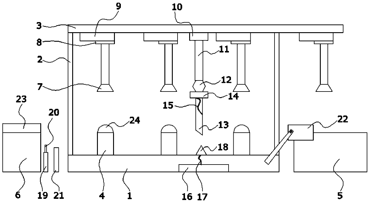
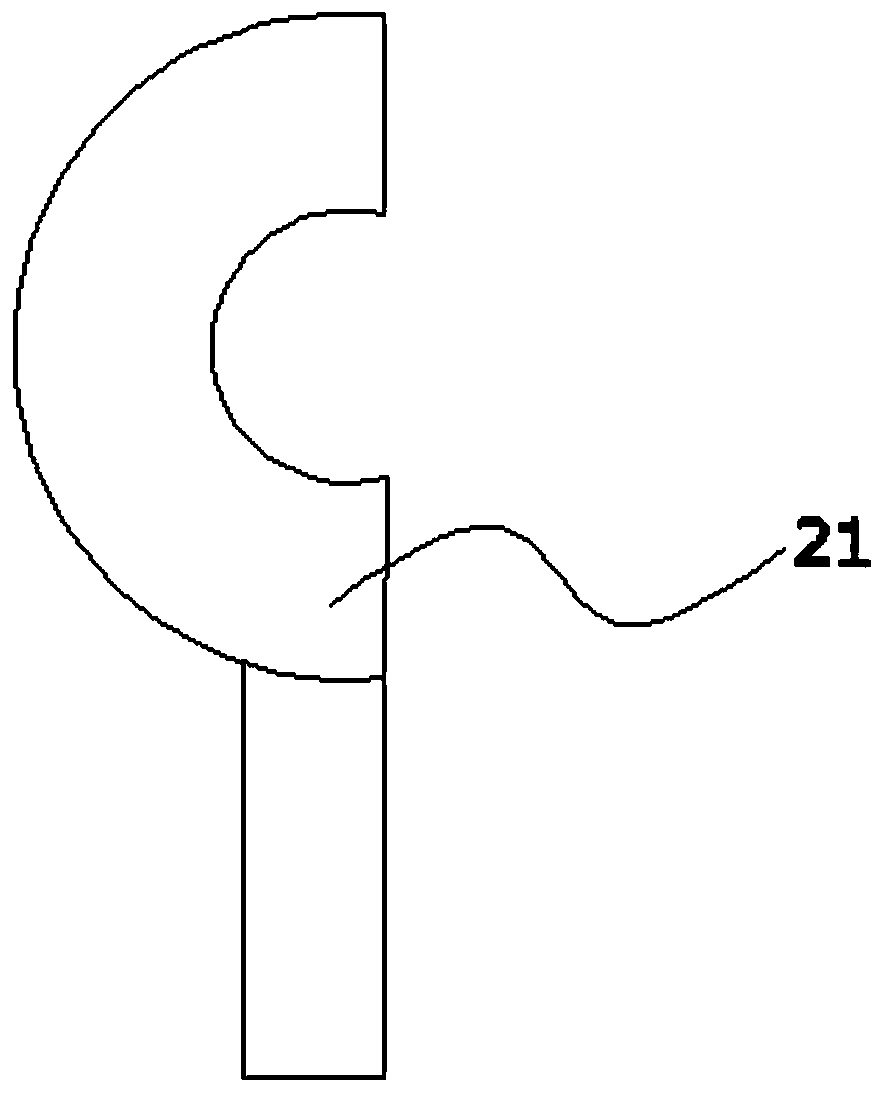
[0021] as follows figure 1 , figure 2 As shown: a strip glass cutting machine includes a base 1, two support rods 2 are arranged side by side on the base 1, the bottom of each support rod 2 is fixedly connected with the base 1, the two support rods 2 A crossbeam 3 is erected between the tops, the lower surface of the crossbeam 3 is opposite to the upper surface of the base 1, and the lower surface of the crossbeam 3 is provided with 4 transmission systems, and the directly below the 3 consecutive transmission systems are uniformly arranged with The base 4, the bottom of the base 4 is fixedly connected with the base 1; the two sides of the base 1 are respectively provided with a first conveyor belt 5 and a second conveyor belt 6, and the moving directions of the first conveyor belt 5 and the second conveyor belt 6 are parallel to each other. The height of the conveyor belt 5 and the second conveyor belt 6 is equal to the height of the base 4; a cutting unit is arranged betwee...


PUM


Abstract

The invention discloses a strip-shaped glass cutting machine. The strip-shaped glass cutting machine comprises a substrate, wherein the substrate is provided with two supporting rods in parallel; the bottom part of each supporting rod is fixedly connected with the substrate; a cross beam is erected between the top parts of the two supporting rods; the lower surface of the cross beam is opposite to the upper surface of the substrate; m+1 transmission systems are arranged on the lower surface of the cross beam; a base is arranged actually under m continuous transmission systems in a one-to-one corresponding way; the bottom part of the base is fixedly connected with the substrate; a first conveyor belt and a second conveyor belt are respectively arranged at two sides of the substrate; movement directions of the first conveyor belt and the second conveyor belt are parallel to each other; the height of the first conveyor belt and the second conveyor belt is equal to that of the base; a cutting unit is arranged between two optional adjacent transmission systems; the movement directions of the cutting units are vertical to the movement directions of the transmission systems. According to the strip-shaped glass cutting machine disclosed by the invention, the situation of glass cracking during a transmission process can be avoided, and the glass is uniformly stressed during a cutting process.

Description

technical field [0001] The invention relates to the technical field of cutting, in particular to a strip glass cutting machine. Background technique [0002] Glass is formed by melting silicon dioxide and other chemicals together (the main production materials are: soda ash, limestone, quartz). A silicate-based non-metallic material that forms a continuous network structure during melting, and gradually increases in viscosity and hardens during cooling to cause it to crystallize. When cutting a block of glass into strip glass, the traditional method is to drive the glass to be transported by the rotation of the conveying roller, and then cut the block glass into strip glass. Because the glass is a fragile product, the glass is very easy to break when the conveying roller rotates and cooperates with the cutting knife. In addition, the uneven cutting force of the traditional cutting machine leads to inconsistent heating of the glass, which increases the risk of glass breakag...

Claims


Application Information

Patent Timeline
Patent Type & Authority Patents(China)
IPC IPC(8): C03B33/03
CPCC03B33/03
Inventor 肖华章
Owner 重庆明斯特玻璃科技有限公司
Learn More