Multi-source feature based visual navigation method of lander

A technology of visual navigation and lander, applied in the field of deep space exploration

Active Publication Date: 2017-09-08
BEIJING INSTITUTE OF TECHNOLOGYGY
View PDF6 Cites 8 Cited by
  • Summary
  • Abstract
  • Description
  • Claims
  • Application Information

AI Technical Summary

Problems solved by technology

[0004] The purpose of the present invention is to solve the problem of estimating the absolute horizontal position of the lande

Method used


Image

  • Multi-source feature based visual navigation method of lander
  • Multi-source feature based visual navigation method of lander
  • Multi-source feature based visual navigation method of lander

Examples


Embodiment Construction

[0056] In order to better illustrate the purpose and advantages of the present invention, the content of the present invention will be further described below in conjunction with the accompanying drawings and examples.

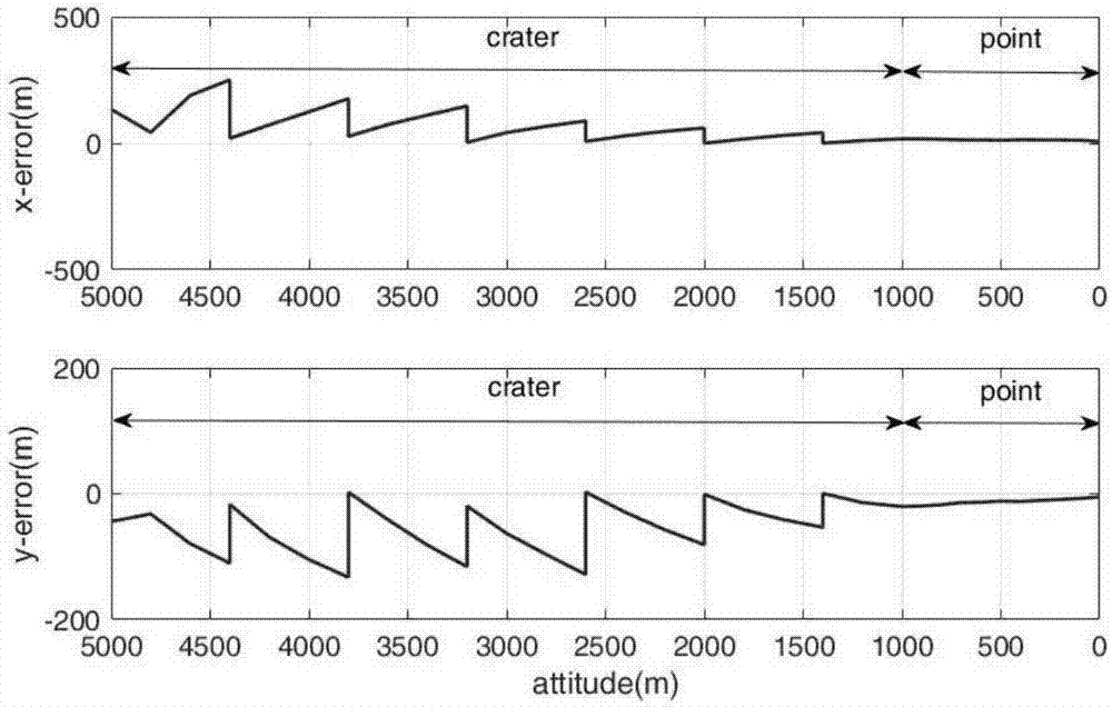
[0057] The present invention uses a lander visual navigation method based on multi-source features in the landing section of Mars as an example for analysis. The measurement parameters of this navigation method have relatively large uncertainties, which can better reflect the practicability of the present invention. The specific implementation method of this example is as follows:

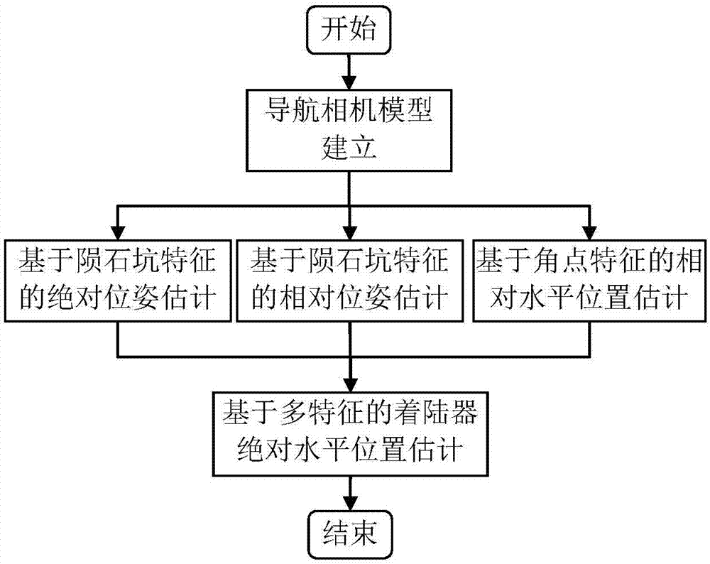
[0058] A lander visual navigation method based on multi-source features, the specific steps are as follows:

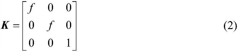
[0059] Step 1: Optical navigation camera model establishment

[0060] The navigation camera model adopted is an ideal pinhole model. feature point x s The position coordinates in the landing point coordinate system are (x s ,y s ,z s ,1) T , feature point x s The co...


PUM


Abstract

The invention relates to a multi-source feature based visual navigation method of a lander, belongs to the technical field of deep space exploration, and aims at solving the problem of estimating the absolute horizontal position of the lander in descending and landing. The method is characterized in that the advantages that meteor crater feature absolute location information is known and landing end corner feature information is rich are utilized, the problems that the quantity of the landing end meteor crater features cannot meet the navigation and positioning condition and the corner feature cannot be applied to the absolute location estimation, can be avoided, and as a result, the stability of navigation algorithm is improved; and the lander can accurately land.

Description

technical field [0001] The invention relates to a lander visual navigation method based on multi-source features, belonging to the technical field of deep space exploration. Background technique [0002] Landing detection and sampling return are the main development directions of deep space exploration in the future. Future small celestial body and Mars exploration missions require the probe to have the ability to land precisely in areas of high scientific value. However, the target celestial body is far away from the earth, and the communication delay is serious, which requires the detector to have the ability of autonomous navigation. At the same time, uncertainties such as insufficient prior information of the target celestial body environment, environmental disturbances, and time-varying dynamic characteristics put forward higher requirements for autonomous navigation systems. [0003] At present, the navigation method based on inertial measurement unit IMU dead positi...

Claims


Application Information

Patent Timeline
IPC IPC(8): G01C21/20
CPCG01C21/20
Inventor 崔平远高锡珍于正湜刘阳朱圣英
Owner BEIJING INSTITUTE OF TECHNOLOGYGY
Why Eureka
Try Eureka