Real-time regression detection system and method for solid rocket propellant burning surface
A solid rocket, real-time detection technology, used in measurement devices, material analysis using sonic/ultrasonic/infrasonic waves, instruments, etc., can solve problems such as large measurement errors and uneven combustion surfaces, to reduce detection errors and improve detection. The effect of precision
- Summary
- Abstract
- Description
- Claims
- Application Information
AI Technical Summary
Problems solved by technology
Method used
Image

Examples
Embodiment Construction
[0021] The specific implementation manners of the present invention will be described below in conjunction with the accompanying drawings.
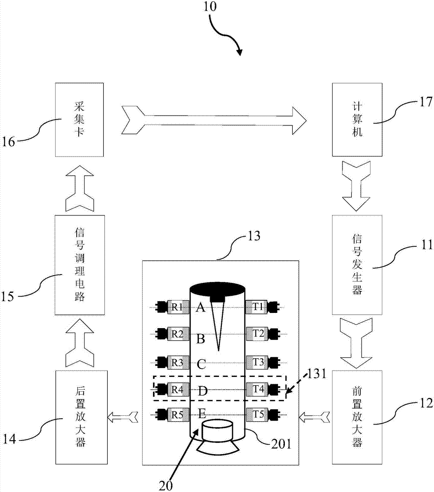
[0022] figure 1 It is a structural schematic diagram of the real-time detection system for the solid rocket propellant combustion surface retreat in this embodiment.
[0023] Such as figure 1 As shown, the solid rocket propellant combustion surface retreat real-time detection system 100 adopts the working mode of non-contact measurement of ultrasonic transducer. It includes a signal generation unit 11 , a pre-amplification unit 12 , a non-destructive testing unit 13 , a post-amplification unit 14 , a signal conditioning unit 15 , a data acquisition unit 16 and a processing control unit 17 .
[0024] The signal generating unit 11 is used for generating an ultrasonic signal as an original pulse signal; the preamplifying unit 12 is used for amplifying the ultrasonic signal.
[0025] The non-destructive testing unit 13 is arranged near the...
PUM
 Abstract
Description
Claims
Application Information
PatSnap Eureka turns technology decisions into work you can execute. Powered by our Innovation Knowledge Graph, it runs expert workflows across engineering, life sciences, materials and intellectual property. Get your review-ready output in minutes.


