
Software development method and system

A software development method and software development technology, applied in software design, program control devices, etc., can solve problems such as increased labor costs, unfavorable growth of team members, and difficulty in merging, so as to reduce labor costs, improve agility and work efficiency. , suitable for promotion effect

Active Publication Date: 2017-09-08
大庆市金东方石油技术开发有限公司
View PDF7 Cites 7 Cited by
  • Summary
  • Abstract
  • Description
  • Claims
  • Application Information

AI Technical Summary

Problems solved by technology

[0005] (1) In order to assign corresponding developers to develop and maintain each layer, it is necessary to equip developers with relevant technologies for each layer, which greatly increases the labor cost; at the same time, because the functions of the logic layer are more complicated and important, so more senior developers are usually required for development and maintenance, and developers with less experience basically have no chance to intervene, which is not conducive to the growth of team members in the long run
[0006] (2) The merging of software with different coding rules is more difficult, and with the increase of the code in a single software, the coupling degree of software with different coding rules will increase sharply, which is very unfavorable for software development and the realization of new requirements
[0009] Another example: the existing network layer needs to be responsible for at least the following two functions: 1. Network request to obtain Json data, 2. Map Json data to obtain a data model, and the network layer has a high degree of coupling
[0010] (3) Since all layers are dependent from top to bottom, the work (development and maintenance) of the lower layer needs to wait for the completion of the work of the upper layer before starting, which leads to poor agility and low work efficiency of the overall development

Method used


Image

  • Software development method and system
  • Software development method and system

Examples


Embodiment Construction

[0036] The present invention will be described in further detail below in conjunction with the accompanying drawings and embodiments.

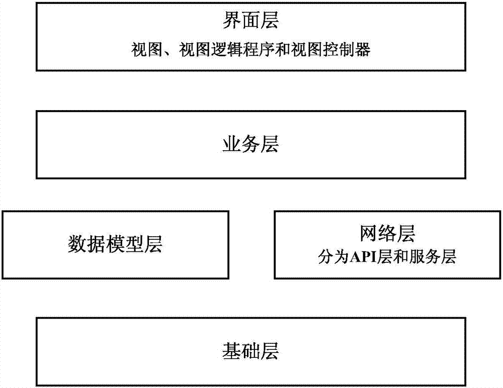
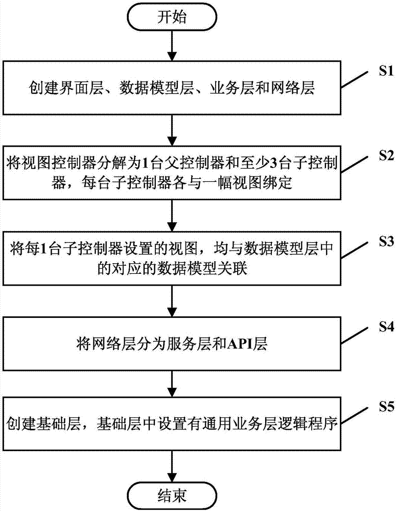
[0037] see figure 1 and figure 2 As shown, the software development method in the embodiment of the present invention includes the following steps:

[0038] S1: Create the working layers associated with the software (interface layer, data model layer, business layer and network layer);

[0039] The interface layer is used to: display the view interface, the interface layer includes the view, the view logic program and the view controller, and the view controller is used to: set the view according to the data model in the data model layer;

[0040] The data model layer is used to: store the data model, the data model includes the local logical data model and the network data mapping model;

[0041] The business layer is used to: provide business interfaces for the view logic program and view controller of the interface layer;

[0042] The ...


PUM


Abstract

The invention discloses a software development method and system and relates to the field of software development. The method comprises the following steps of: creating a working layer associated with software, wherein the working layer comprises an interface layer, a data model layer, a business layer and a network layer; the interface layer is used for exhibiting a view interface; the interface layer comprises a view, a view logical program and a view controller; the view controller is used for configuring a view according to a data model in the data module layer; the data module layer is used for storing a data model which comprises a local logical data model and a network data mapping model; the service layer is used for providing a service interface for the view logical program of the interface layer and the view controller; the network layer is used for mapping Json data to the network data mapping model after requiring the network to return the Json data. The method provided by the invention can reduce the human cost during software development and reduce the coupling degree of the software.

Description

technical field [0001] The invention relates to the field of software development, in particular to a software development method and system. Background technique [0002] In the process of software development, with the increase of the project scale and the number of developers, the coding style and module calling rules adopted by different projects are often different, which leads to various styles of code and modules appearing in the final project. Project coupling Higher and higher. When maintaining the developed software, it is difficult for developers to change unfamiliar modules, and it takes a long time for new development members to learn different coding rules. [0003] In order to facilitate the development and maintenance of software, the existing software development methods are generally as follows: usually "horizontal layering" is carried out on large-scale projects first, for example, the client is divided into multiple layers: interface layer, logic layer, ...

Claims


Application Information

Patent Timeline
IPC IPC(8): G06F9/44
CPCG06F8/22
Inventor 孙林张文明陈少杰
Owner 大庆市金东方石油技术开发有限公司
Learn More