Single-live line on-state power taking circuit

A single live wire and circuit technology, applied in the field of electronics, can solve problems such as the inability to intelligently judge whether the power-taking circuit is successful, the inability to identify whether the load is good or bad, and the effect of affecting the use of lamps, so as to solve the problem of judging that the lamp power is too small and avoid charging. The effect of high voltage and solving the problem of judging the quality of lamps and lanterns

Active Publication Date: 2017-09-08
姚朝霞 +1
View PDF14 Cites 4 Cited by
  • Summary
  • Abstract
  • Description
  • Claims
  • Application Information

AI Technical Summary

Problems solved by technology

Although in this utility model, by adopting the electromagnetic relay control circuit with low power consumption, the requirements for power taking can be reduced, but the power taking circuit uses the power supply voltage VCC2 to provide signal C for the voltage comparator, and signal B is obtained by taking In this way, if the triode Q2 is mistakenly turned on, the power-taking circuit will also have current loss in the case of static power-taking, and the power-taking circuit cannot intelligently judge whether the power-taking circuit is successfully taken If there are multiple load LEDs, if one of the load LEDs is damaged, the other load LEDs will flicker, which will affect the use effect of the lamp.

Method used


Image

  • Single-live line on-state power taking circuit
  • Single-live line on-state power taking circuit

Examples


Embodiment Construction

[0025] The following are specific embodiments of the present invention and in conjunction with the accompanying drawings, the technical solutions of the present invention are further described, but the present invention is not limited to these embodiments.

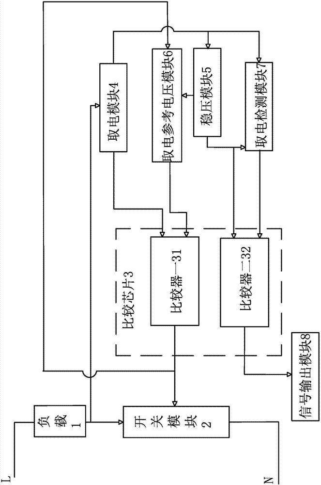
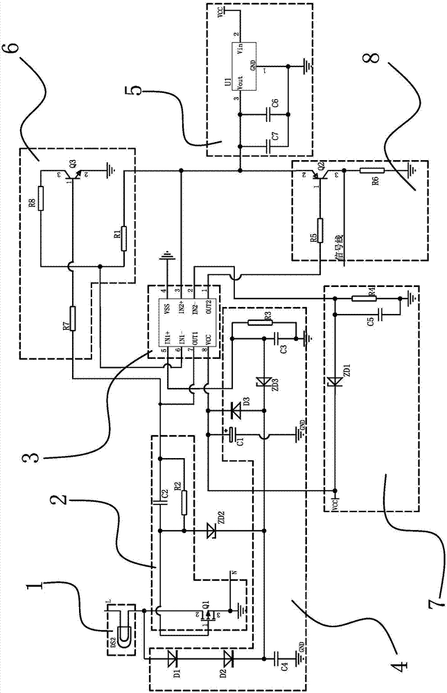
[0026] Such as figure 1 As shown, the single live wire open-state power-taking circuit includes a switch module 2, a power-taking module 4 for outputting a power-taking voltage VCC, a voltage stabilizing module 5, a power-taking reference voltage module 6, and a power-taking detection module 7. The signal of whether the electricity fetching is successful is sent to the signal output module 8 of the controller and the comparison chip 3 with a comparator 31 and a comparator 2 32, wherein one end of the switch module 2 is connected to the live wire through the load 1, and the other end is connected to the neutral wire. connection, the control terminal of the switch module 2 is connected to the output terminal of the comparato...


PUM


Abstract

The invention provides a single-live line on-state power taking circuit, and belongs to the technical field of electronics. By the single-live line on-state power taking circuit, the problem of low reliability of a circuit in the prior art is solved. The single-live line on-state power taking circuit comprises a comparison chip and a power taking module, a voltage stabilization module, a signal output module, a switch module, a power taking detection module and a power taking reference voltage module which are connected with the comparison chip, wherein the switch module is also connected with the power taking module, the voltage stabilization module is also connected with the power taking reference voltage module, the power taking module is also connected with an input end of the voltage stabilization module and the power taking detection module and comprises an electrolytic capacitor C1, the power taking detection module comprises a voltage stabilization diode ZD1, and the power taking module is connected with a negative electrode of the voltage stabilization diode ZD1 of the power taking detection module through a positive electrode of the electrolytic capacitor C1 and is connected with the input end of the voltage stabilization module though the positive electrode of the electrolytic capacitor C1. By the power taking circuit, the working current under a condition of static power taking can be reduced, and the application performance of a load is improved.

Description

technical field [0001] The invention belongs to the field of electronic technology, and relates to a single live wire open-state power-taking circuit. Background technique [0002] The single live wire switch is an electronic wall switch, which is a replacement product of the traditional mechanical button wall switch. It can realize more intelligent and more convenient functions, and the user can control the lighting by touch. However, since the single live wire switch is connected to the power grid in series to provide power for the control circuit, that is to say, whether it is in the standby state or when the switch is turned on, it is necessary to ensure that there is current flowing through the control circuit. When the current is too large, it will cause the electrical appliances to fail to work normally. Common problems such as lamps will flicker intermittently, while the current is too small and the smart switch will not work properly. Therefore, this involves the si...

Claims


Application Information

Patent Timeline
Patent Type & Authority Applications(China)
IPC IPC(8): H05B37/02
CPCH05B47/10Y02B20/40
Inventor 张志潮郑万荣
Owner 姚朝霞
Why Eureka
Try Eureka