Method for operating an electrically operable suction valve

A suction valve, no current technology, applied in the direction of electrical control, engine control, fuel injection control, etc., can solve the problem of increased wear of the drive mechanism components, achieve the effect of reducing load and improving robustness

Active Publication Date: 2021-03-02
ROBERT BOSCH GMBH
View PDF7 Cites 0 Cited by
  • Summary
  • Abstract
  • Description
  • Claims
  • Application Information

AI Technical Summary

Problems solved by technology

The consequence is increased wear on the drive train components

Method used


Image

  • Method for operating an electrically operable suction valve
  • Method for operating an electrically operable suction valve

Examples


Embodiment Construction

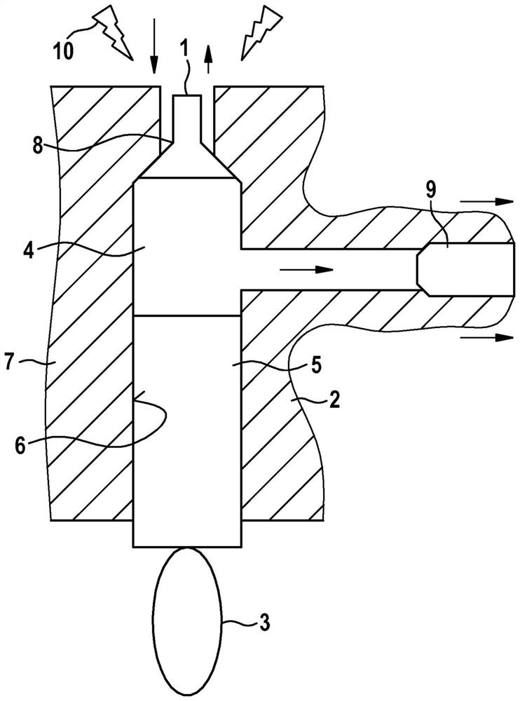
[0022] exist figure 1 A high-pressure pump 2 for a common rail injection system, shown very schematically in FIG. In the cylinder bore 6 of the housing part 7. The pump piston 5 can be driven in a stroke movement via the drive mechanism 3 , which is in the present case designed as a cam drive. During the delivery stroke of the pump piston - during which the volume in the high-pressure element chamber 4 becomes smaller - the fuel present in the high-pressure element chamber 4 is compressed and then supplied via the high-pressure outlet 9 to the high-pressure accumulator ( not shown). The high-pressure element chamber 4 is filled with fuel via an electrically actuatable suction valve 1 , which is presently designed as a valve that opens when there is no current flow. The suction valve 1 has a valve tappet 8 which can be opened into the high-pressure element chamber 4 of the high-pressure pump 2 and which can be actuated via a magnetic actuator (not shown). As a valve that op...


PUM


Abstract

The invention relates to a method for actuating an electrically actuatable suction valve (1) for regulating the delivery of a high-pressure pump (2) in a fuel injection system of an internal combustion engine, in particular in a common rail injection system quantity. According to the invention, at least when the internal combustion engine is started, the suction valve (1) is actuated as a function of at least one parameter which influences the lubrication conditions in the drive chamber (3) of the high-pressure pump (2).

Description

technical field [0001] The invention relates to a method for actuating an electrically actuatable suction valve for regulating the delivery rate of a high-pressure pump in a fuel injection system of an internal combustion engine, in particular in a common rail injection system. Background technique [0002] High-pressure pumps in fuel injection systems, in particular common rail injection systems, are used to deliver fuel at high pressure. For this purpose, the high-pressure pump has at least one pump element with a high-pressure element chamber in which fuel is compressed. The fuel delivered at high pressure is then supplied to a high-pressure accumulator, the so-called rail, via a high-pressure outlet. Fuel under high pressure is then injected into the combustion chamber of the internal combustion engine via an injection valve connected to the high-pressure accumulator. [0003] The high-pressure element chamber of the high-pressure pump is usually filled via a suction v...

Claims


Application Information

Patent Timeline
Patent Type & Authority Patents(China)
IPC IPC(8): F02D41/38F02M59/36
CPCF02D41/062F02D41/3845F02D2041/2055F02D2200/0602F02D2200/0606F02D2200/101F02M59/366
Inventor A·克勒F·内克尔
Owner ROBERT BOSCH GMBH
Why Eureka
Try Eureka