Cam carrying and blowing-dedusting device

A technology of blowing dust and cams, applied in the direction of cleaning methods, cleaning methods and utensils, chemical instruments and methods using gas flow, etc., to achieve the effects of novel structure, improved handling efficiency, and stable and effective handling cams

Inactive Publication Date: 2017-09-12
JIASHAN JINYI PRECISION CASTING
View PDF6 Cites 5 Cited by
  • Summary
  • Abstract
  • Description
  • Claims
  • Application Information

AI Technical Summary

Problems solved by technology

After the cam production is completed, it needs to be transported and cleaned, and the traditional conveyor line cannot meet such requirements

Method used


Image

  • Cam carrying and blowing-dedusting device
  • Cam carrying and blowing-dedusting device
  • Cam carrying and blowing-dedusting device

Examples


Embodiment Construction

[0027] In order to make the technical means, creative features, goals and effects achieved by the present invention easy to understand, the present invention will be further elaborated below in conjunction with illustrations and specific embodiments.

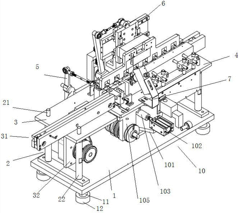
[0028] Such as Figure 1 to Figure 5 As shown, a cam-carrying blowing dust removal device proposed by the present invention includes a base 1, and the left and right sides of the upper end of the base 1 are fastened with stays 2 by bolts, and the surface of the stays 2 has two concave Groove, the inner wall of the groove is a thread structure, the upper end of the stay 2 is screwed with a support rod 21, the top and bottom of the support rod 21 are threaded structure, the upper end of the support rod 21 is screwed with a working platform, The outside of the support rod 21 is also sleeved with a stabilizing tube 22. The working platform includes a left working platform 3 and a right working platform 4, and the left working platfo...


PUM


Abstract

The invention provides a cam carrying and blowing-dedusting device. The device comprises a base. Supporting battens are fastened to the left side and the right side of the upper end of the base through bolts correspondingly. Two grooves are formed in the surface of each supporting batten. The inner wall of each groove is of a threaded structure. The upper ends of the supporting battens are in screw connection with supporting rods. The top ends and the bottoms of the supporting rods are all of threaded structures. The upper ends of the supporting rods are in screw connection with a working platform. The outsides of the supporting rods are further sleeved with stabilizing barrels. The working platform comprises a left working platform body and a right working platform body connected with the left working platform body through fasteners. The left working platform body comprises a conveying part and a drive part. The conveying part is located at the upper end of the left working platform body, and the drive part is located at the lower end of the left working platform body. A material distributor, a cam propelling and moving device and a deduster are further arranged on the right working platform body.

Description

technical field [0001] The invention relates to the field of cam cleaning, in particular to a cam carrying air blowing and dedusting device. Background technique [0002] At present, there are few devices about cam handling and dust removal in existing equipment, and most of the work of cleaning the cam is still done manually, which greatly reduces the cleaning and production efficiency. [0003] Moreover, since the cam itself is used as a part of some large equipment, it must be ensured that its surface is free from wear during the production process, which is very demanding for production. After the cam production is completed, it needs to be transported and cleaned, and the traditional conveyor line cannot meet such requirements. [0004] Therefore, it is necessary for us to improve such a structure to overcome the above-mentioned defects. Contents of the invention [0005] The object of the present invention is to provide a cam carrying air blowing dust removal devic...

Claims


Application Information

Patent Timeline
Patent Type & Authority Applications(China)
IPC IPC(8): B08B5/02B08B13/00
CPCB08B5/02B08B13/00
Inventor 吴金明
Owner JIASHAN JINYI PRECISION CASTING
Why Eureka
Try Eureka