A chuck power-assisted composite biaxial dynamic friction stir welding method

A friction stir and welding method technology, applied in welding equipment, non-electric welding equipment, metal processing equipment, etc., can solve the problems of low welding speed, wear of stirring head, heavy equipment, etc., to improve welding speed, improve strength, and reduce welding. The effect of defects

Active Publication Date: 2019-06-28
XI AN JIAOTONG UNIV
View PDF10 Cites 0 Cited by
  • Summary
  • Abstract
  • Description
  • Claims
  • Application Information

AI Technical Summary

Problems solved by technology

Therefore, in the special high temperature environment of friction stir welding, when welding metal materials with high melting point, the wear of the stirring head is serious and the equipment is generally heavy and complicated.
In addition, when welding materials with high melting point and large thickness, the welding speed is often low

Method used


Image

  • A chuck power-assisted composite biaxial dynamic friction stir welding method
  • A chuck power-assisted composite biaxial dynamic friction stir welding method
  • A chuck power-assisted composite biaxial dynamic friction stir welding method

Examples


Embodiment Construction

[0020] The present invention will be described in detail below in conjunction with the accompanying drawings.

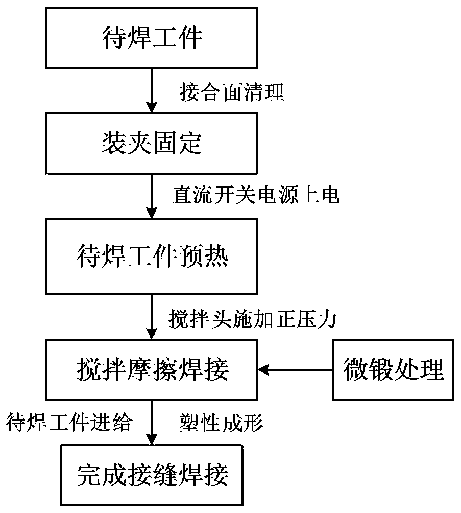
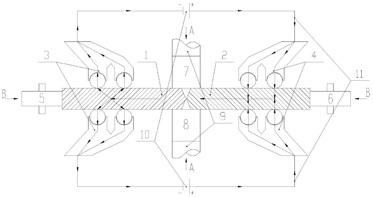
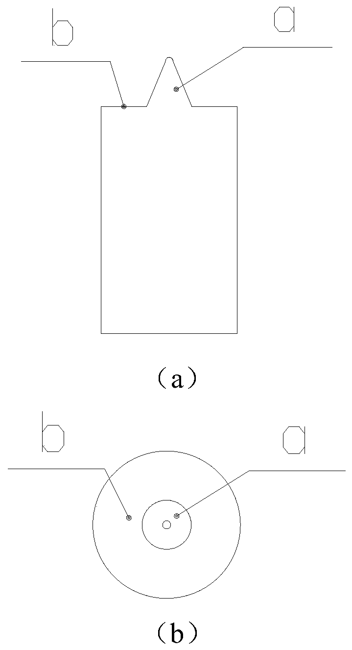
[0021] refer to figure 1 , figure 2 , image 3 and Figure 4 , a collet power supply assisted compound biaxial dynamic friction stir welding method, comprising the following steps:

[0022] 1) Clamping of workpieces to be welded: pass the first workpiece 1 to be welded and the second workpiece 2 to be welded through the negative dynamic clamping head 3, the positive dynamic clamping head 4, the first guide preload wheel 5 and the second guide preloader. The tightening wheel 6 is clamped and fixed on the welding workbench. The negative dynamic clamping head 3 and the positive dynamic clamping head 4 limit the first workpiece 1 to be welded and the second workpiece 2 to be welded between the first stirring head 7 and the second stirring head. 8 degrees of freedom in the axis A-A direction, the first guide pretension wheel 5 and the second guide pretension wheel 6 ...


PUM


Abstract

The invention discloses a chuck power supply auxiliary compound double-axis dynamic friction stir welding method. Positive and negative electrode dynamic clamping heads and a guide pretightening wheel are adopted to finish clamping of workpieces to be welded; a direct-current switch power supply is used for providing high-density current into the workpieces to be welded; metals in joints of the workpieces to be welded are preheated; stirring heads rotating at high speed are inserted in two sides of the joints; positive pressure is applied to the metals in the joints through shaft shoulders, so that the metal materials in the joints are softened; the stirring heads enable the metal structures in the joints to achieve a plastified state under the stirring effect; meanwhile, a ultrasonic exciter is adopted to finely forge the plastified metals, so that grains of the metal structures in the joints are refined; the workpieces to be welded are fed along with a welding worktable in the directions of the joints; and the plastified metals are continuously filled in a cavity formed after movement of stirring needles under the stirring and extruding effects of the stirring heads, and are gradually cooled to condense as welding lines. The method relieves the wear of the stirring heads, increases the welding thickness, accelerates the welding speed, and reduces the welding defects.

Description

technical field [0001] The invention belongs to the technical field of friction stir welding and forming, and in particular relates to a dual-axis dynamic friction stir welding method with power supply auxiliary for chucks. Background technique [0002] Friction stir welding (FSW) is a solid phase welding technology, originally used for the connection of low melting point metals (such as aluminum alloys and magnesium alloys, etc.), because there is no melting of materials in the FSW process, so this technology can avoid traditional fusion welding Common problems such as cracks, pores and deformation, and have low requirements for operation and equipment. Although the research on friction stir welding technology has been more and more in-depth, but there are still deficiencies in this technology. [0003] Friction stir welding mainly stirs the workpiece through the stirring head, and relies on frictional heat to heat the metal around the joint of the workpiece to a plastic s...

Claims


Application Information

Patent Timeline
Patent Type & Authority Patents(China)
IPC IPC(8): B23K20/12
CPCB23K20/122B23K20/1245
Inventor 赵升吨张鹏范淑琴王永飞董朋
Owner XI AN JIAOTONG UNIV
Why Eureka
Try Eureka