

Right-angle cutting chatter analysis modeling method
A technology of right-angle cutting and modeling method, which can be used in measuring/indicating equipment, program control, instruments, etc., and can solve problems such as cumbersomeness and low accuracy of cutting force coefficients
- Summary
- Abstract
- Description
- Claims
- Application Information
AI Technical Summary
Problems solved by technology
Method used
Image

Examples
Embodiment Construction
[0058] The present invention will be further described in detail below in conjunction with the accompanying drawings and examples. The following examples are explanations of the present invention and the present invention is not limited to the following examples.
[0059] Such as Figure 1~3 As shown, a right-angle cutting chatter analytical modeling method, including the following steps:
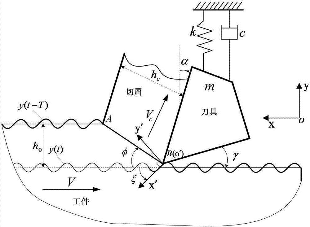
[0060] Step 1, establish a dynamic model of chatter in right-angle cutting
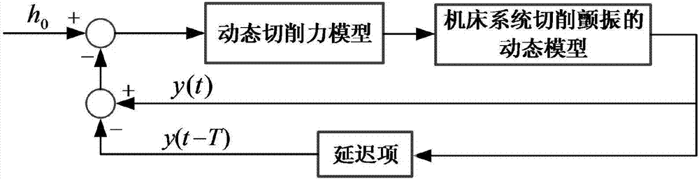
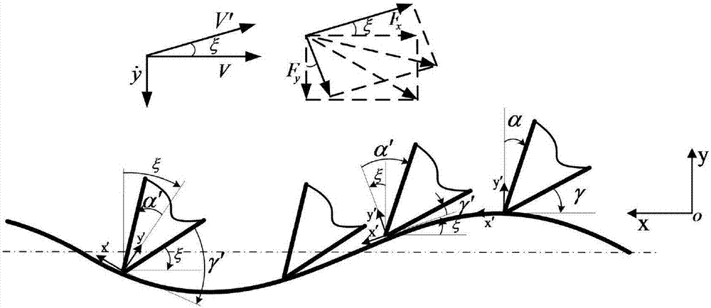
[0061] Determine the geometric parameters of the tool, the rake angle α, the unit is deg, the relief angle γ, the unit is deg; select the cutting parameters, cutting speed V, the unit is m / min, the feed rate f t , the unit is mm / r, the cutting width b, the unit is mm; in the process of metal cutting, the change of cutting thickness will lead to the fluctuation of cutting force, the cutting force and cutting thickness change according to a specific cycle, and form a closed loop The feedback system calculates the d...
PUM
 Abstract
Description
Claims
Application Information