Improved concrete transmission and transformation electric power circuit pole and production method thereof
A technology for power lines and production methods, applied in the directions of reinforcement molding, building types, molds, etc., can solve the problems of poor sealing of the end anchoring plate, easy bumping of the end face of the root of the pole, and running of the end face of the tip and root of the pole. , to achieve the effect of reducing the probability of end face bumping, reducing slurry running defects, and reducing the probability of end face being knocked off
Inactive Publication Date: 2017-09-12
GUANGXI POWER LINE EQUIP FACTORY
View PDF6 Cites 0 Cited by
- Summary
- Abstract
- Description
- Claims
- Application Information
AI Technical Summary
Problems solved by technology
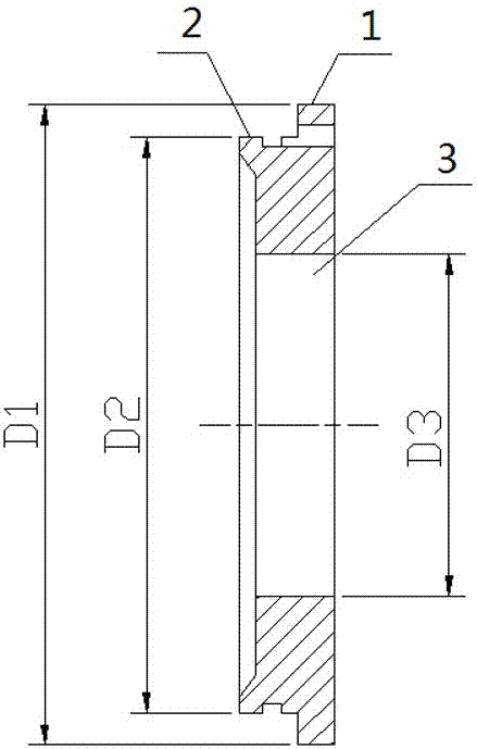
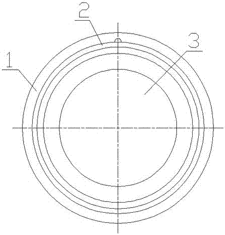
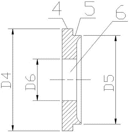
[0002] The prestressed poles of power transmission and transformation lines that we usually see are generally cylinders with one big end and a small end. After being installed on site, the small head is upward, the top is called slightly, and the bottom with a big head is called the root. The root is equipped with an anchor plate. It is further divided into flat end anchor plates and boss end anchor plates. Ordinary poles use flat end anchor plates, and prestressed poles use boss end anchor plates. The currently used flat end anchor plates and boss end anchor plates are the largest The disadvantage is that the sealing of the anchor plate at the end is poor, and the grout retaining metal plate at the tip is also flat. When the concrete is poured and centrifuged, it is easy to cause the grout defect on the tip and root end of the pole, and it is easy to produce grout defects during hoisting or The end face of the pole root is easy to be damaged during transportation; the installed concrete power pole is also ugly, so the manufacturers of concrete power line poles do not want this situation to happen
Method used
View moreImage
Smart ImageViewing Examples
Examples
Embodiment 2
[0041] The manufacturing method is the same as that of Embodiment 1, and the metal plate 11 of the grout blocking at the tip and the anchor plate 13 at the root are 12CrNi3A.
Embodiment 3
[0043] The manufacturing method is the same as that of Example 1, and the tip grout metal plate and the root anchor plate 13 are 12CrNi3A.
Login to View More PUM
 Abstract
The invention relates to an improved concrete transmission and transformation electric power circuit pole and a production method thereof. The method comprises the steps that an electric pole cage-shaped framework is manufactured; a steel wire is wound automatically; an electric pole top part baffle board and a root part anchoring plate are manufactured; the electric pole cage-shaped framework is subjected to concrete grouting and centrifuging; and electric pole maintenance is conducted, an electric pole with the top diameter portion being in a circular truncated cone shape and a base being provided with a flange is obtained, the diameter portion of a metal baffle board body is anchored and attached with an electric pole steel mold top part end plate, the root part anchoring plate and the electric pole steel mold end plate are anchored and attached, the electric pole top part baffle board and the root part anchoring plate are bushed into the inner wall of an electric pole steel mold, and an inner hole is formed in the middle of the metal board body. By the adoption of the method, the electric rod root part and the top part can be made flat after being formed, and the root part end face impact probability of the electric pole in the hoisting or transporting process is lowered; and meanwhile, in the centrifugal forming process of the electric pole, due to the fact that a top part baffle board boss and an anchoring plate chamfer boss are bushed into the electric pole steel mold, a sealing effect is achieved, and the grout runout phenomenon of the electric pole top part and root part end face is reduced.
Description
technical field [0001] The invention relates to the technical field of production of power transmission and transformation power line products, in particular to an improved production method of concrete power transmission and transformation power line poles. Background technique [0002] The prestressed poles of power transmission and transformation lines that we usually see are generally cylinders with one big end and a small end. After being installed on site, the small head is upward, the top is called slightly, and the bottom with a big head is called the root. The root is equipped with an anchor plate. It is further divided into flat end anchor plates and boss end anchor plates. Ordinary poles use flat end anchor plates, and prestressed poles use boss end anchor plates. The currently used flat end anchor plates and boss end anchor plates are the largest The disadvantage is that the sealing of the anchor plate at the end is poor, and the grout retaining metal plate at th...
Claims
Login to View More Application Information
Patent Timeline
 Patent Type & Authority Applications(China)
IPC IPC(8): B28B21/68B28B21/80E04H12/12
CPCB28B21/68B28B21/80E04H12/12
Inventor 林贤杰覃枫黄家德杨周潘宏林文锋农天高
Owner GUANGXI POWER LINE EQUIP FACTORY
Features
- R&D
- Intellectual Property
- Life Sciences
- Materials
- Tech Scout
- Unparalleled Data Quality
- Higher Quality Content
- 60% Fewer Hallucinations
Learn More Browse by: Latest US Patents, China's latest patents, Technical Efficacy Thesaurus, Application Domain, Technology Topic, Popular Technical Reports.
© 2025 PatSnap. All rights reserved.Legal|Privacy policy|Modern Slavery Act Transparency Statement|Sitemap|About US| Contact US: help@patsnap.com


