
Rear mold structure of injection mold

A technology of injection mold and back mold, which is applied in the field of back mold structure of injection mold, can solve problems such as difficulty in mold design, and achieve the effects of reducing the probability of bruising, high processing efficiency, and high processing precision

Inactive Publication Date: 2016-11-09
SUZHOU HUACHUAN PLASTIC MOLD PROD FACTORY
View PDF5 Cites 0 Cited by
  • Summary
  • Abstract
  • Description
  • Claims
  • Application Information

AI Technical Summary

Problems solved by technology

Some parts have special shapes, so it is difficult to design the mold, and the mold structure must be designed reasonably

Method used


Image

  • Rear mold structure of injection mold
  • Rear mold structure of injection mold

Examples


Embodiment Construction

[0013] The present invention is described below in conjunction with accompanying drawing.

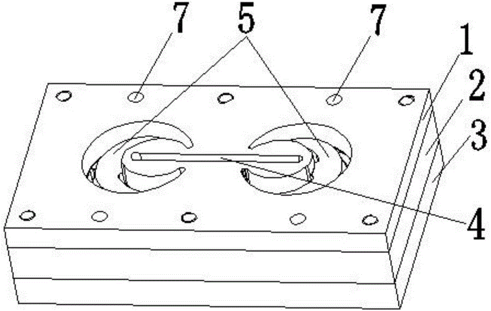
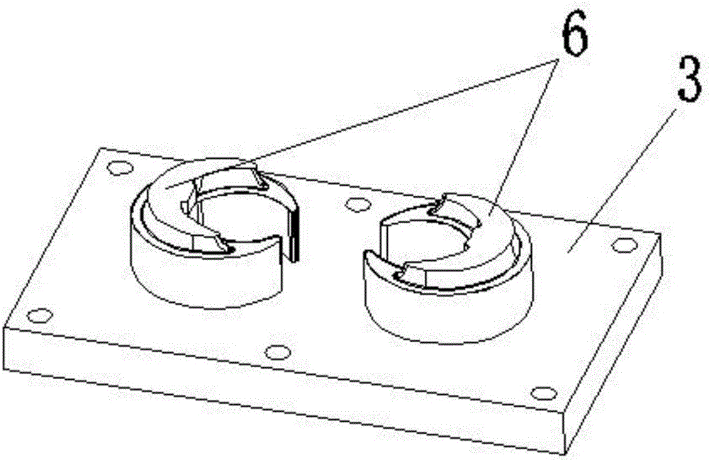
[0014] The back mold structure of the injection mold of the present invention, as attached Figure 1-2 As shown, it includes a cavity plate 1, a rear core plate 2 and a rear core backing plate 3 which are stacked sequentially from top to bottom; The cavity plate 1 and the rear mold core plate 2 are provided with two symmetrical insert cavities 5; the insert cavities 5 are in a left-right symmetrical crescent shape, and their crescent depressions are opposite; the insert cavities 5 vertically penetrate the cavity plate 1 and the rear mold core plate 2; the two insert cavities 5 are located on the left and right sides of the transverse flow channel 4; the cavity plate 1 is also provided with two left-right symmetrical latent feeding ports (not shown in the drawings drawn); the two latent feed ports respectively connect the insert cavities 5 on the left and right sides with the transverse...


PUM


Abstract

The invention discloses a rear mold structure of an injection mold. The rear mold structure comprises a mold cavity plate, a rear mold core plate and a rear mold core backing plate which are sequentially laminated from top to bottom, and further comprises a cross runner. The mold cavity plate and the rear mold core plate are provided with two insert cavities which are symmetrical left and right. The insert cavities are in the shape of a left-right symmetrical crescent, and crescents are recessed and opposite to each other. The insert cavities vertically penetrate through the mold cavity plate and the rear mold core plate. The two insert cavities are located in the left side and right side of the cross runner. The mold cavity plate is further provided with two concealed feeding inlets which are symmetrical left and right. The two concealed feeding inlets make the insert cavities located in the left side and right side communicate with the cross runner. Two rear mold inserts are inlaid in the rear mold core plate. The rear mold core backing plate is made of hard metal. Hard materials are additionally arranged at the bottoms of the inserts so that the inserts can be prevented from retreating in production due to mold base deformation. The rear mold structure is used on the injection mold and used for manufacturing crescent-shaped injection products, and working accuracy is high. Meanwhile, two products can be produced at the same time, and thus working efficiency is high.

Description

technical field [0001] The invention relates to the field of mold structures for plastic products, in particular to a rear mold structure of an injection mold with a crescent-shaped cavity. Background technique [0002] Injection mold is an important process equipment for the production of various industrial products. With the rapid development of the plastics industry and the promotion and application of plastic products in aviation, aerospace, electronics, machinery, ships and automobiles and other industrial sectors, injection molds are widely used in various industries middle. The traditional injection mold consists of a moving mold and a fixed mold. The moving mold is installed on the movable template of the injection molding machine, and the fixed mold is installed on the fixed template of the injection molding machine. During injection molding, the movable mold and the fixed mold are closed to form the gating system and the cavity, and the movable mold and the fixed ...

Claims


Application Information

Patent Timeline
Patent Type & Authority Applications(China)
IPC IPC(8): B29C45/32
CPCB29C45/2602B29C45/32
Inventor 谢永华
Owner SUZHOU HUACHUAN PLASTIC MOLD PROD FACTORY
Learn More