Waste plastic pelleting unit

A technology of waste plastics and granulation, applied in the direction of coating, etc., can solve the problems of uncontrollable feeding amount and uneven feeding speed, etc., and achieve the effect of ensuring health, small installation space and saving space resources

Inactive Publication Date: 2017-09-12
绵阳立新科技发展有限公司
View PDF4 Cites 4 Cited by
  • Summary
  • Abstract
  • Description
  • Claims
  • Application Information

AI Technical Summary

Problems solved by technology

[0010] The purpose of the present invention is: in order to solve the problem that the feeding speed of the existing plastic granulation unit is not uniform and the feeding amount cannot be controlled, the present invention provides a waste plastic granulation unit, which transmits materials through the conveying auger to achieve uniform feeding , to ensure that the obtained plastic products are of good quality

Method used


Image

  • Waste plastic pelleting unit
  • Waste plastic pelleting unit
  • Waste plastic pelleting unit

Examples


Embodiment 1

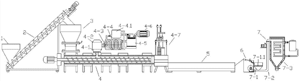
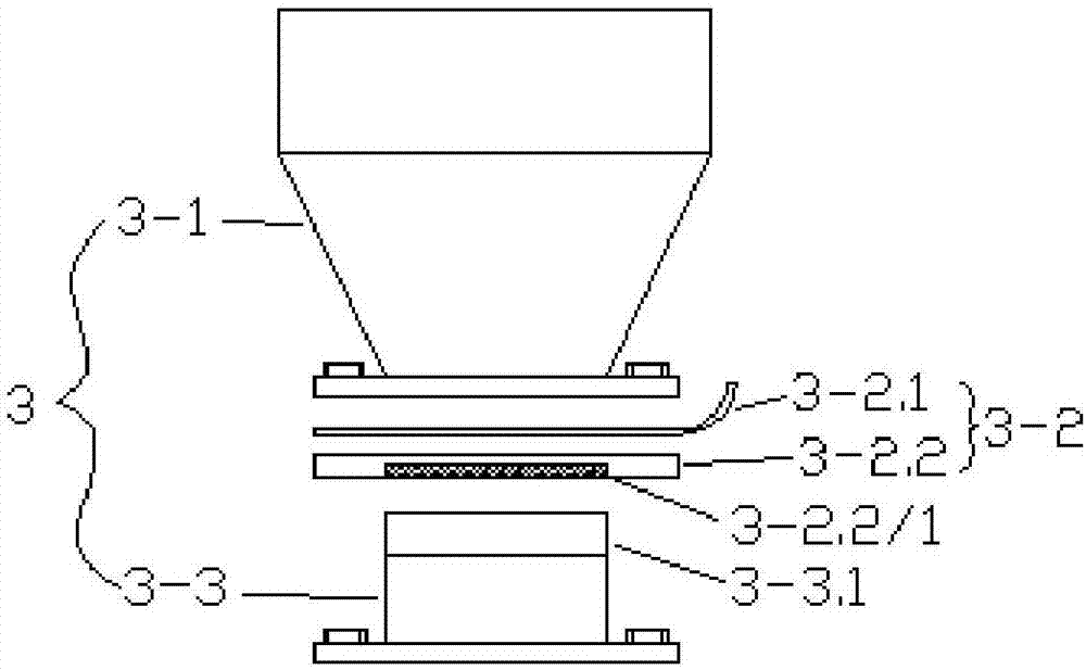
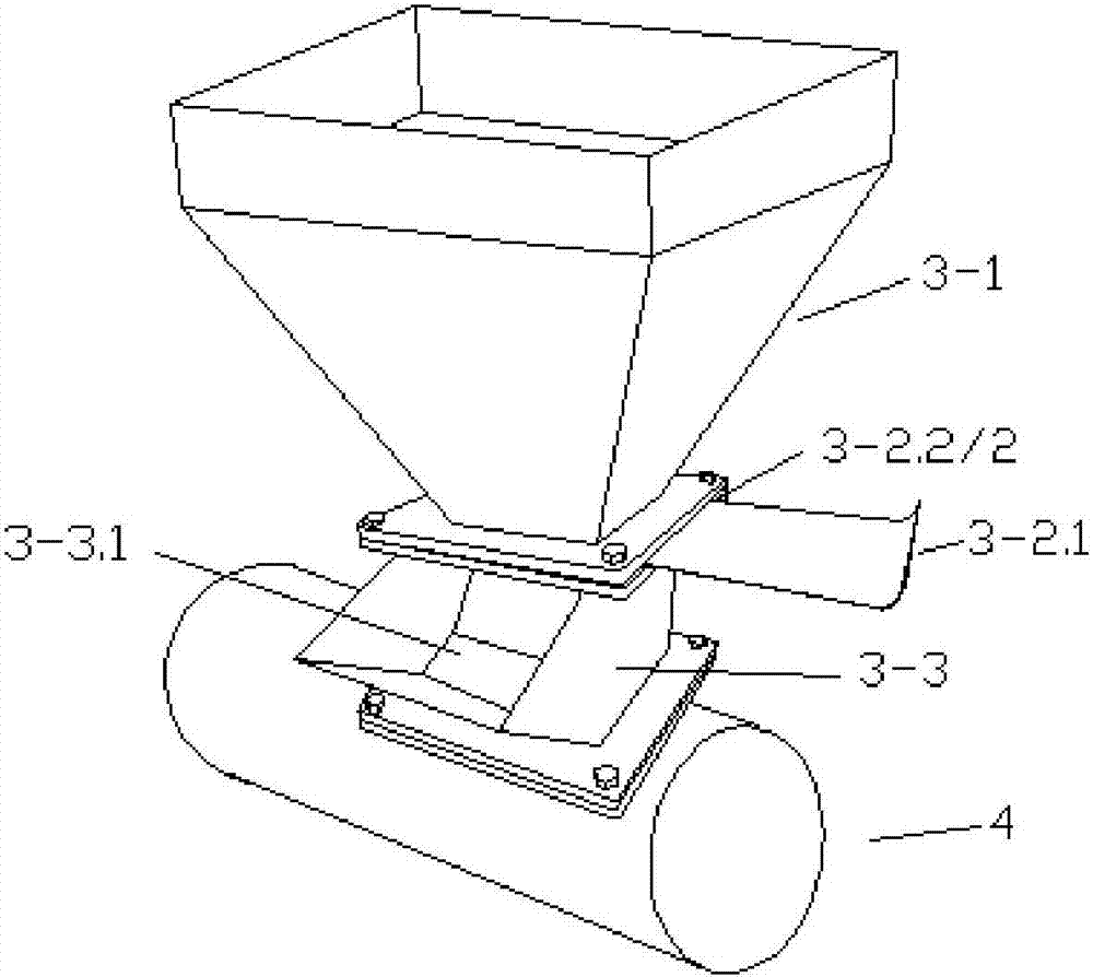
[0048] Such as Figure 1 to Figure 6 As shown, this embodiment provides a waste plastic granulation unit, which includes a storage box 1, a conveying auger 2, a feeding device 3, a screw extruder 4, a cooling device 5, a granulator 6 and a connecting device connected in sequence. The feeding device 7, the feeding device 3 includes a first feed hopper 3-1 and a second feed hopper 3-3, and an intercepting assembly 3-2 is arranged below the first feeding hopper 3-1, and the intercepting assembly 3-2 Including the intercepting plate 3-2.1 and the connecting plate 3-2.2 hollowed out in the middle, the connecting plate 3-2.2 is provided with a groove 3-2.2 / 2 for the sliding of the intercepting plate 3-2.1, hollowed out in the middle of the connecting plate 3-2.2 A feed filter screen 3-2.2 / 1 is detachably arranged at the center, and the lower part of the intercepting assembly 3-2 is connected with the second feed hopper 3-3, and the second feed hopper 3-3 is provided with a residual ...

Embodiment 2

[0057] Such as Figure 7 to Figure 10 As shown, the present embodiment is further optimized on the basis of embodiment 1, specifically:

[0058] The intercepting assembly 3-2 is provided with an electromagnetic vibrator 3-4 that drives the feed filter screen 3-2.2 / 1 to vibrate, and the connection between the first feed hopper 3-1 and the intercepting assembly 3-2 is provided with a first rubber A shock absorbing layer 3-2.3, a second rubber shock absorbing layer 3-2.4 is provided at the connection between the intercepting assembly 3-2 and the second feed hopper 3-3;

[0059] An activated carbon adsorption layer 4-6.1 is arranged in the ultraviolet lamp box 4-6, and the activated carbon adsorption layer 4-6.1 is arranged at intervals with the ultraviolet lamp;

[0060] The cleaning assembly A4-7.6 and the cleaning assembly B for cleaning the filter screen A4-7.4 and the filter screen B4-7.5 are arranged symmetrically on the double slide rail installation frame 4-7.3, and the c...


PUM


Abstract

The invention discloses a waste plastic pelleting unit and relates to the technical field of plastic processing equipment. The waste plastic pelleting unit comprises a storage box, a transmission auger, a feeding device, a screw extruder, a cooling device, a granulator and a receiving device which are connected in sequence, wherein the feeding device comprises a first feeding hopper and a second feeding hopper; a flow intercepting assembly for controlling material flow rate is arranged under the first feeding hopper and comprises a flow intercepting plate and a connecting plate; the middle of the connecting plate is hollow; a groove allowing the flow intercepting plate to slide is formed in the connecting plate; the flow intercepting plate can control the material flow rate through sliding along the groove; a feeding filter screen is detachably arranged in the middle hollow part of the connecting plate; the second feeding hopper is connected with the flow intercepting assembly; a remainder viewport is formed in the second feeding hopper; the second feeding hopper is connected with a machine barrel of the screw extruder; and the material quantity in the machine barrel can be observed in real time through the remainder viewport. The waste plastic pelleting unit transmits material through the transmission auger to realize uniform feeding and ensure that the obtained finished plastic product is high in quality.

Description

technical field [0001] The invention relates to the technical field of plastic processing equipment, and more specifically relates to a waste plastic granulation unit. Background technique [0002] The recycling and resource development of waste plastics is derived from a deep understanding of the environment and resources, and is a production method that reduces the pollution of waste plastics to the environment and reduces the waste of resources. Realizing the recycling and recycling of waste plastics is a major event that benefits the country and the people. According to estimates, every ton of waste plastics used can save more than 85% of energy and 70-80% of processing costs compared with raw materials, which is equivalent to Save 20 tons of oil. [0003] At present, the method of recycling waste plastics usually includes the following steps: [0004] Step 1. Wash and dry the waste plastic; [0005] Step 2, and then use the screw extruder in the plastic regeneration ...

Claims


Application Information

Patent Timeline
Patent Type & Authority Applications(China)
IPC IPC(8): B29B9/06B29B9/16B29B13/04B29C31/00B29C47/10B29C47/68B29C47/76B29C48/76
CPCB29B9/06B29B9/16B29B13/045B29C31/00B29C48/285B29C48/6912B29C48/767
Inventor 何其勇
Owner 绵阳立新科技发展有限公司
Why Eureka
Try Eureka