Rubber track

A rubber crawler and crawler technology, applied in the field of rubber crawlers, can solve the problems of being unable to suppress crack growth, unable to suppress growth, etc., and achieve the effect of suppressing the generation of cracks

Active Publication Date: 2017-09-12
SUMITOMO RUBBER IND LTD
View PDF8 Cites 0 Cited by
  • Summary
  • Abstract
  • Description
  • Claims
  • Application Information

AI Technical Summary

Problems solved by technology

[0006] However, the rubber crawler of the above-mentioned Patent Document 1 can suppress the occurrence of cracks in the vicinity of the bases of the lugs, but when a crack occurs, the adhesive rubber layer and the rubber core are separated, so that the growth of the crack cannot be suppressed.
In addition, the rubber track of Patent Document 1 cannot suppress the growth of cracks in the rubber core itself.

Method used


Image

  • Rubber track
  • Rubber track
  • Rubber track

Examples


Embodiment Construction

[0025] Hereinafter, one embodiment of the present invention will be described based on the drawings.

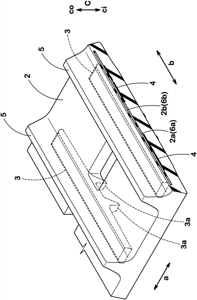
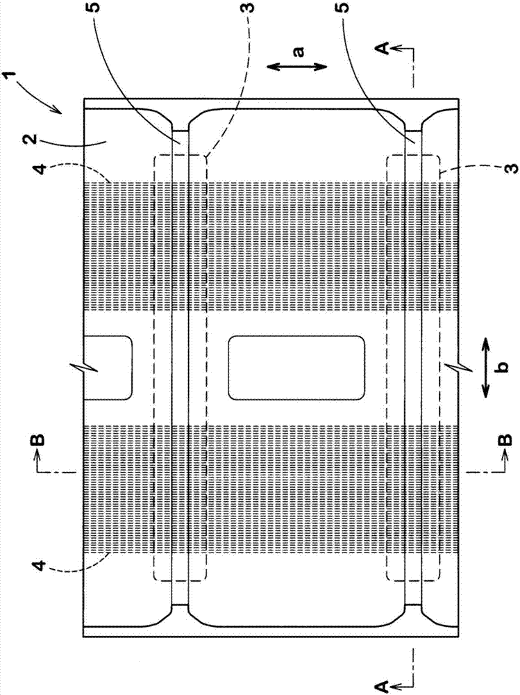
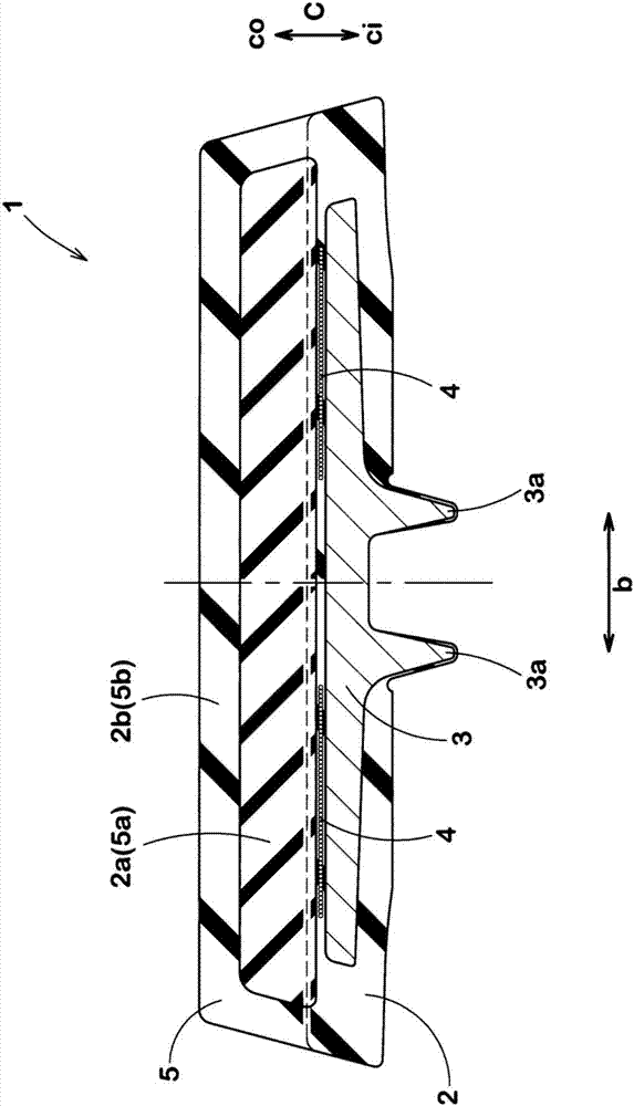
[0026] figure 1 It is a perspective view which shows the rubber crawler 1 of this embodiment. Such as figure 1 As shown, the rubber crawler 1 of the present embodiment includes a crawler main body 2 formed of rubber in an endless belt shape, a plurality of mandrels 3 embedded in the crawler main body 2 , and a tensile body 4 .

[0027] In this specification, the track circumferential direction is the rotation direction of the rubber track 1, which is equivalent to figure 1 The reference sign a indicates the direction. In addition, the track width direction is the axial direction of the driving wheel, floating wheel and roller when the rubber track 1 is installed on the vehicle, which is equivalent to figure 1 The direction indicated by the reference sign b. In addition, the track thickness direction is a direction perpendicular to the track circumferential direction and ...


PUM

PropertyMeasurementUnit
Thicknessaaaaaaaaaa
Hardnessaaaaaaaaaa
Hardnessaaaaaaaaaa

Abstract

The invention provides a rubber track. Crack-resisting performance and crack generation resisting performance can be considered simultaneously. The rubber track (1) comprises a track main body (2) and a tension-resisting body (4). The track main body is in shape of a ring belt made of rubber and is equipped with multiple lugs (5) protruding towards the track outer circumferential side (co). The tension-resisting body (4) is embedded in the track main body (2) and continuously extends along the track circumferential direction (a). The track main body (2) comprises a base part tread layer (2a) and a top part tread layer (2b). The base part tread layer is arranged on the track outer circumferential side (co) and is continuous along the track circumferential direction (a). The top part tread layer (2b) is arranged on the track outer circumferential side (co) and is continuous along the track circumferential direction (a). The base part tread layer (2a) has a base part lug (5a) protruding towards the interior of each lug (5).

Description

technical field [0001] The present invention relates to a rubber crawler having both crack resistance and crack growth resistance. Background technique [0002] Conventionally, a rubber crawler is known, which has a crawler main body formed of rubber in an endless belt shape, and a tensile body embedded in the crawler main body. In order to transmit driving force and traction force during running, a plurality of lugs protruding toward the outer peripheral side of the crawler belt are formed on the crawler belt main body. The tensile body extends continuously along the circumferential direction of the crawler belt in order to maintain the tension of the crawler belt main body. [0003] The main body of the crawler utilizes the tension of the tensile body and maintains its shape even while running. On the other hand, the lugs located closer to the outer peripheral side of the track than the tensile member may be greatly deformed by ground contact during running. Due to this...

Claims


Application Information

Patent Timeline
IPC IPC(8): B62D55/24B62D55/253
CPCB62D55/24B62D55/253
Inventor 小松宙梦
Owner SUMITOMO RUBBER IND LTD
Why Eureka
Try Eureka